Yes,the one where you move the capacitor negatives,makes a big difference.Discussion can be found in the F6 thread.= picodumb mod ?

C3M0065090D

good to have confirmed one as good, even if not having DC functionality in SOA graph
Last edited:
The picodumb mod for the source resistors looks like this:

It is only applied to the upper Mosfet M1. I ended up with a smaller value at R5, and suggest you use high precision thick film resistors. It may be applied by carefully lifting the Source leg of M1 and inserting the resistance between the lifted leg and the PCB mounting hole. Make sure you have some spare output Mosfets on hand before trying this one.
This mod seems to change the relationship between H2 and H3. The stock F6 may sound a little analytical to some. Changing the source resistance in this way introduces a small amount of asymmetrical distortion to the output.
Original poster was whinging about His F6 sounding too rolled off in the high end.
Exactly the opposite situation.
Exactly the opposite situation.
In the original F6 R1 is 0.56 ohms and R2 is 0.47 ohms,there is not 2 resistors as r5 and r6 in the above schematic.I built an F6 and mine had the original R1 and R2.I moved both capacitor negatives.In the original if you move only the R1 negative you wind up with 10x the distortion,about 0.5% at 1W vs 0.05%.In the above you wind up with about 3x the distortion (.15% at 1W)The picodumb mod for the source resistors looks like this:
View attachment 1083252
It is only applied to the upper Mosfet M1. I ended up with a smaller value at R5, and suggest you use high precision thick film resistors. It may be applied by carefully lifting the Source leg of M1 and inserting the resistance between the lifted leg and the PCB mounting hole. Make sure you have some spare output Mosfets on hand before trying this one.
This mod seems to change the relationship between H2 and H3. The stock F6 may sound a little analytical to some. Changing the source resistance in this way introduces a small amount of asymmetrical distortion to the output.
I am not sure I read about it, has anyone tried improving psu for the amp front end? i.e. adding something like a 200ohm series resistor + decoupling cap from amp psu, or a dedicated regulated psu to the 2sk170/2sj74 pair? Also, what would be best voltage for these?
You could have a look at the voltage regulators that are part of the "Cedarburg" input stage option in the M2X thread - the zener is set at 30 volts for the AD797 chip but this could possibly be changed/increased for the jfet's operation (unsure, needs homework!) and the main O/P fets rails increased, etc.
... or perhaps, look at using the "Input stage 7" of the same M2X design is replacement for the input jfets and choice of ICs with/without the input stage rail modulation ....
... or perhaps, look at using the "Input stage 7" of the same M2X design is replacement for the input jfets and choice of ICs with/without the input stage rail modulation ....
https://www.firstwatt.com/pdf/prod_f7_man.pdf
Where I got the idea of positive current feedback from. Just as usable for adding some low end muscle to a F6. But it does a lot more then that with the sound.
Where I got the idea of positive current feedback from. Just as usable for adding some low end muscle to a F6. But it does a lot more then that with the sound.
I did not see your speakers mentioned. What speakers?I’ve built a F6 last year from diyaudio boards, transistors and input transformers. I find the sound warm and topend slightly rolled off. The bias is 520-30mV. I have a Schiit Aegir and this is the observation when I compare both.
my queastion is how can I take the F6 further up a notch? Keeping the same tonal balance in midrange but open up the highs a bit and a slightly tighter bottom end?
Will replacing the 1000uF caps to Mundorfs help? How about building dual mono power supplies feeding dedicated amp channel?
thanks
To add, what's the source? My F6 was drastically different stepping up from a Schiit BiFrost to the Benchmark DAC3.I did not see your speakers mentioned. What speakers?
An improvement would be an update to revision 2, especially the addition of P3 which allows to adjust the harmonic spectrum (soundcard and software like Arta or REW is sufficient). Ideally the PCBs from the store should implement the R2 changes.
Have a look here as well: https://www.diyaudio.com/forums/pass-labs/258613-diyaudio-firstwatt-f6-post6039613.html
Have a look here as well: https://www.diyaudio.com/forums/pass-labs/258613-diyaudio-firstwatt-f6-post6039613.html
Attachments
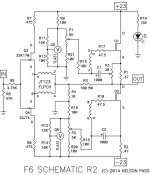
Thanks for posting this R2 schematic Georg, it's good to go back to papa's original post too.An improvement would be an update to revision 2, especially the addition of P3 which allows to adjust the harmonic spectrum (soundcard and software like Arta or REW is sufficient). Ideally the PCBs from the store should implement the R2 changes.
Have a look here as well: https://www.diyaudio.com/forums/pass-labs/258613-diyaudio-firstwatt-f6-post6039613.html
I was thinking something similar to adding R7 and R8 in my post #26 above, plus a 200uF (?) decoupling capacitor if it makes sense from drain of the Jfets to ground?
It might be worth adding provision for 2 input jfet's source <-> transformer pins1/2 resistors and also provision for positive feedback too to expand the possible variations ...
Plus, the ground connection of the possible 220uF capacitors should be grounded to the pcb central 0v power point, not the signal ground, if possible.
Plus, the ground connection of the possible 220uF capacitors should be grounded to the pcb central 0v power point, not the signal ground, if possible.
Decoupling caps would not hurt yes. Or even some cap multiplier.Thanks for posting this R2 schematic Georg, it's good to go back to papa's original post too.
I was thinking something similar to adding R7 and R8 in my post #26 above, plus a 200uF (?) decoupling capacitor if it makes sense from drain of the Jfets to ground?
Would that also work with the IRFP240? The FQH44N10 are unobtainium.The picodumb mod for the source resistors looks like this:
View attachment 1083252
It is only applied to the upper Mosfet M1. I ended up with a smaller value at R5, and suggest you use high precision thick film resistors. It may be applied by carefully lifting the Source leg of M1 and inserting the resistance between the lifted leg and the PCB mounting hole. Make sure you have some spare output Mosfets on hand before trying this one.
This mod seems to change the relationship between H2 and H3. The stock F6 may sound a little analytical to some. Changing the source resistance in this way introduces a small amount of asymmetrical distortion to the output.
Certainly, splitting the source resistance between the connection to the 1000 uF capacitor works as well with IRF Mosfets.
I am investigating the use of IXTQ75N10P Mosfets in place of the FQH44N10. The newer Mosfets have a high transconductance figure, plus reasonable Gate capacitance and Gate charge figures. And they require a higher threshold voltage to achieve the bias currents we typically want in an F6. I'm still working on that.
I am investigating the use of IXTQ75N10P Mosfets in place of the FQH44N10. The newer Mosfets have a high transconductance figure, plus reasonable Gate capacitance and Gate charge figures. And they require a higher threshold voltage to achieve the bias currents we typically want in an F6. I'm still working on that.
I just ordered some here yesterday. Should be delivered next week.Would that also work with the IRFP240? The FQH44N10 are unobtainium.
https://www.ebay.de/itm/235001190218
I never really liked the F6 as is. To me it sounded a bit slow and pudgy. What helped was increasing the PSU voltage to 40V and in order to not kill the input buffer I used the Jung/Didden SuperRegs I had, set for 20V.I am not sure I read about it, has anyone tried improving psu for the amp front end? i.e. adding something like a 200ohm series resistor + decoupling cap from amp psu, or a dedicated regulated psu to the 2sk170/2sj74 pair? Also, what would be best voltage for these?
Apart from that I increased feedback (decreasing might also help, the gain structure in my system led towards an increase).
It's been awhile but I seem to remember my F6 build, both with IRF MOSFETS and SemiSouth JFETS, just didn't seem right and fell apart a bit with complex / busy music. Could have been an issue with my own build, it went un-resolved, so I'm not sure. It got pulled out after a few months and I moved onto something else. My system needs to be able to play any type of material without apologies...
- Home
- Amplifiers
- Pass Labs
- Improve F6 further