KCHANG should upgrade to a non-polar, for audio...
I did already.🙂 See my opening post. I replaced the original no-name polar caps with Nichicon Muse UES bi-polar caps. Maybe the difference I heard was not imaginary after all.
Last edited:
Another option is connecting 2 caps in series + -x- + and then apply a negative biasing voltage of a few volts through a 1 or 2 m ohm resistor. The time i did this I didn't apply the biasing voltage till the amp was on and playing music then I hooked a 9v battery as the biasing voltage. There was no pop or thump I just noticed the music getting clearer.
tantalum to be a lot worse for signals than normal electro...
Most tantalum types also have rather high ESR.
I prefer to use amps that have no capacitor in the feedback loop, or a very small one, film/foil part.
Recently have been quite satisfied using my favorite polar, electrolytic w/o bypass. It has a very low distortion profile with mostly 2nd hd. I am quite surprised at how good it is sounding considering in an SAE 2300 from 40 years ago.
Recently have been quite satisfied using my favorite polar, electrolytic w/o bypass. It has a very low distortion profile with mostly 2nd hd. I am quite surprised at how good it is sounding considering in an SAE 2300 from 40 years ago.
If you keep the feedback resistor a higher value you can decrease size of feedback capacitor.
I think around 1uf is doable in polyester etc.
I think around 1uf is doable in polyester etc.
If you keep the feedback resistor a higher value you can decrease size of feedback capacitor.
I think around 1uf is doable in polyester etc.
The penalty is paid in Noise thou...
Thanks for the comments.
Using your circuit components, the capacitor distortion is generated by C2. It is injected into the amplifier via R28, not directly into Vfb. Won't the gain be - R35/R28? It is different from non-inverting input which we all know is 1 + R35/R28, my mistake.
Regards
Master Tibouchina.
I don't have that circuit in font of me, but you are correct that any distortion generated from that cap is attenuated by the two resistors of the feedback network before it gets to the inv input.
That attenuation would be Rf/(Rg+Rf) which, in an amp with say 25 times gain, would be like 24/25. So there is a correction, but not significant.
And once it is at -inv input, the gain of that error signal to the output is indeed Aol, NOT Acl. By definition, Vout = Aol*(Vin-Vfb), with Vfb being the signal at the inv input, independent of what you do externally with feedback and whatnot.
Jan
Last edited:
And also here, a bit more structured ;-)
Cyril Bateman's Capacitor Sound articles | Linear Audio NL
Jan
-30dB (3%) distortion might be approaching "atrocious" yet even that seems fine to SET fans.KCHANG said:So -60dB is not "atrocious" enough for you?
If it was low order distortion, which it probably would be coming from a cap, then I would be quite happy as it is extremey unlikely that I would hear it.You'd not be proud of designing an amp that has -86dB of distortion at 500mVac input (so ~ 12.5W assuming a gain of 20 into an 8ohm load), would you?
THD and IMD come from the same thing: nonlinearity. The only difference between them is the relevant frequencies, which may receive different filtering. The bottom cap in the feedback network has a similar role to a coupling cap, so you cannot directly compare with a cap used as a high signal level filter such as a speaker crossover. You have to do maths to compare, as I did above.
Using a physically large cap at this point may simply swap one problem (a tiny amount of nonlinearity) for another problem (noise/hum/interference pickup).
who in the DIY community would have access to a spectrum analyser?
Anybody with a $ 120 sound card has.
Jan
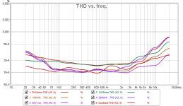
I have QA401 and I design and build an 120w/8ohm amplifier with THD=0.0003% at 1khz and THD=0.0020% at 20khz (20w/8ohm power test) with capacitor of 1.000uF/16v Nichicon EP in the negative feedback. I tried without capacitor and the results are very similar into. Considering the price and simplicity of the capacitor, it's hard to choose another solution.
This is exactly what I was saying earlier.
When I talk to the amp designer, I said I would upgrade this part first, based on logic and what others say about the feedback loop.
He told me that it would not make any difference because the feedback was self correcting... we talk about 22 db + here.
So I changed the cap to the best nichicon possible, made 0 difference in sound, then I bypassed it, also inaudible, then with his help I installed thermal sockets over input stage complementary transistors to stabilize the DC drift, and after some efforts was able to remove the cap and have a near stable DC output of a few milivolts. It did not change a thing to the sound.
note that a full DC gain amp (with capacity of 10+ amps DC out bursts) without any capacitor in the signal path including the input and feedback is a 100% potential speakers killer, I had to turn off the amp to connect cables etc and turn the amp first off in the chain of components, any 1 VDC at input could mean 20V of DC out
Last edited:
He told me that it would not make any difference because the feedback was self correcting... we talk about 22 db + here.

Isn't that sad, several people go out of their way to explain why feedback network errors are NOT self-correcting, and the myth just lives on ...
Jan
Jan
It depends on how familiar a person is with control theory. Not necessarily sad. Basic conceptual errors are made by a lot of people in here so safety in numbers (or in the absence of numbers! 😛). What frustrates me no end is those "experts" who people revere for publishing books who make shameful conceptual and mathematical mistakes.🙄Isn't that sad, several people go out of their way to explain why feedback network errors are NOT self-correcting, and the myth just lives on ...
Jan
Feedback is not a magic elixir. Obviously, any distortion between the sense point (the speaker output) and the subtractor input will be multiplied by the closed loop gain of the amplifier and appear inverted at the sense point. And this depends on frequency and stability. There are many other ways feedback will not work perfectly and can make the sound worse. It is extremely challenging, in my experience, to apply bags of feedback to a circuit and maintain its musicality. This is probably why tube amps and Krells and Pass Labs try to keep the excess loop gain pretty low.
Isn't that sad, several people go out of their way to explain why feedback network errors are NOT self-correcting, and the myth just lives on ...
Jan
And so the forum goes...
Still, the contributors should be thanked for an educational thread for those paying attention.
- Home
- Amplifiers
- Solid State
- Importance of the quality of the DC-blocking feedback capacitor?