The supergainclone from Cordell's book also has a nice trick to avoid large value feedback caps but it's for an inverting config.
The supergainclone from Cordell's book also has a nice trick to avoid large value feedback caps but it's for an inverting config.
Actually you triggered my memory about a most relevant article I almost forgot about, in my own Linear Audio series! I must be getting old.
Here it is, complementary 😎
His figure 5b is what Jonathan showed in post # 26. But this time with a narrative ;-)
Jan
Attachments
Last edited:
Don´t you think it´s cheap enough to try and listen?
My speakers have only film caps, if I don't have a film cap I use a polar cap temporarily, I just said that non-polar caps sound bad.
Non polar caps are just 2 polar caps whatever how they are made and how good they measure, you just place 2 polar caps which sounds worse than just one polar cap.
For an unexplained reason, non-polar caps are bad in XO.
if you install a non-polar based on thd -100db measurements, you are completely missing the issues here, it is what is audible, not what is measurable, like in most audio where 60db is the threshold of audible distortion.
gabdx, alayn91..
DC-blocking feedback capacitor is something totally different from capacitor in XO.. Think about AC voltage across capacitor terminals, and AC current.
DC-blocking feedback capacitor is something totally different from capacitor in XO.. Think about AC voltage across capacitor terminals, and AC current.
nonsens..🙄 For sure it is measurable.you are completely missing the issues here, it is what is audible, not what is measurable
You got a bit lucky with the stability, in general power amplifiers are not unity gain stable, but this one clearly was. I would guess that the designer was very conservative in picking the Vas integrator cap value.Why was I able to get away with this? Bruno says that the only problem with massive amounts of NFB is how to implement it. Was it possible just because the amplifier is such a simple design?
I would also guess that you were running way short of full song, given that unity gain would need the best part of 40V up the input to reach clipping, stability issues often show at large inputs so that may have worked in your favour.
Regards, Dan.
Indeed, FILTER caps by definition have meaningful amounts of signal voltage developed across them, COUPLING caps do not (If you size them correctly)!gabdx, alayn91..
DC-blocking feedback capacitor is something totally different from capacitor in XO.. Think about AC voltage across capacitor terminals, and AC current.
nonsens..🙄 For sure it is measurable.
A passive speaker crossover is about the worst case situation for a cap, nowhere else in audio does the combination of low impedance, large value and signal voltage across the cap exist.
In band filters are different to COUPLING usage and of course different optimisations apply. This just comes down to understanding the function of the part in the circuit and picking the best one for that position, different applications, different tradeoffs.
You got a bit lucky with the stability, in general power amplifiers are not unity gain stable, but this one clearly was. I would guess that the designer was very conservative in picking the Vas integrator cap value.
I would also guess that you were running way short of full song, given that unity gain would need the best part of 40V up the input to reach clipping, stability issues often show at large inputs so that may have worked in your favour.
Regards, Dan.
Hi Dan, this is it Mosfet Amplifier (EMM Jun 81)
You are right I was only running it at line level. As I said Mooly simmed it and it was fine
have meaningful amounts of signal voltage developed across them
??? why??? I can filter a digital signal, I can filter 1V, 1nv, does this means it is no longer a filter cap? In a sensitive driver, only 0.1V is required at the input, the cap could see only maybe 0.05 V max.
There is no such definition of filter caps and coupling caps as per VOLTAGE and CURRENT...
this is absurd
Coupling caps can be used with the function of filtering DC AND filtering frequencies... a coupling caps at the output of a power amp will have more DC and AC than the 'filter' cap in the XO.
Actually you triggered my memory about a most relevant article I almost forgot about, in my own Linear Audio series! I must be getting old.
Here it is, complementary 😎
His figure 5b is what Jonathan showed in post # 26. But this time with a narrative ;-)
I´ve seen that "capacitor trick" implemented on several Luxman power amps from the ´80s that were very well regarded. Like the M-02 and others.
Also simulated in LTSpice, comparing that with sim THD results using DC-Servo and blocking caps.
The only demand seems to be that the input transistor should be FETs.
I'm sure it can be used on line preamps, though I never saw anyone who did. It should be tricky to implement on a RIAA preamp.
I have some asc Luxman models that I can upload if anyone is interested.
Coupling cap is used only for blocking DC , but not to influence AC (must simply have big enough value not to create frequency dependant divider with load impedance, so here is no meaningful AC voltage across cap in audio band.. ). Coupling is not filtering... If it is not clear to you, so..Coupling caps can be used with the function of filtering DC AND filtering frequencies
A filter cap will normally have a significant fraction of the signal voltage across it. A coupling cap normally will not. An exception is if a coupling cap is being used as a dominant LF filter. This, like how feedback works, is audio electronics basics.gabdx said:There is no such definition of filter caps and coupling caps as per VOLTAGE and CURRENT...
No. The output coupling cap will typically have much less AC across it than a crossover cap. Maybe you struggle with the words 'across it'?Coupling caps can be used with the function of filtering DC AND filtering frequencies... a coupling caps at the output of a power amp will have more DC and AC than the 'filter' cap in the XO.
I have a novice question, hopefully not disturbing this interesting discussion. .
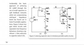
I'm trying to understand how the capacitor in this figure 5b is calculated. The author says the two circuits have the same low frequency behaviour, -3dB roll off I guess. For figure 5a it's 15,9Hz if I get it right. For figure 5b only way the 0,22μF capacitor to reach that is to work against 45,522 ohm. Is it 4.59M/(102.23k/1k)?Actually you triggered my memory about a most relevant article I almost forgot about, in my own Linear Audio series! I must be getting old.
Here it is, complementary 😎
His figure 5b is what Jonathan showed in post # 26. But this time with a narrative ;-)
Jan
Attachments
Interesting question, I don't have the answer right here. I think you should look at the signal across the cap. The voltage across the cap is very low, because both sides are at about Vin.
The impedance it works against I believe includes the opamp input impedance, but I am not sure.
I'll see if I can reach Kendall, to ask him! Thanks for bringing it up.
Jan
The impedance it works against I believe includes the opamp input impedance, but I am not sure.
I'll see if I can reach Kendall, to ask him! Thanks for bringing it up.
Jan
Coupling cap is used only for blocking DC , but not to influence AC (must simply have big enough value not to create frequency dependant divider with load impedance, so here is no meaningful AC voltage across cap in audio band.. ). Coupling is not filtering... If it is not clear to you, so..
Well, it depends 🙂
What you say is usual in Hi Fi amps and preamps but the exact opposite is quite common in Musical instrument ones.
Which are often used overloaded or clipping so "small" coupling caps are used all over the place.
Some extreme (and famous, go figure) examples are are Marshsall: 2200 pF feeding a 470k volume pot, VOX : 470 pF into 470k , Orange and its iconic "frequency selector" , a 6 position rotary switch selecting from 220 pF to .022 or thereabouts.
Just do the Math on them and you'll see they aggressively cut Bass; sometimes below 600 Hz or so.
I have a novice question, hopefully not disturbing this interesting discussion.
I'm trying to understand how the capacitor in this figure 5b is calculated. The author says the two circuits have the same low frequency behaviour, -3dB roll off I guess. For figure 5a it's 15,9Hz if I get it right. For figure 5b only way the 0,22μF capacitor to reach that is to work against 45,522 ohm. Is it 4.59M/(102.23k/1k)?
If I got my math right the pole frequency is at
Fp = 1/(2 * pi * (R4*(R3 + R5))/(R3 + R4) * C2 ) = 15.9Hz
Fc~=1/(2pi*R5*C2) * R3/R4.
The effective value of R5 appears as 1/100th of the resistor value because it sees 100x the voltage at the capacitor's right side pin.
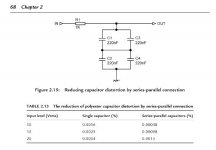
Noise performance will by compromised big time, that's the price to pay for smallish capacitor values.
The effective value of R5 appears as 1/100th of the resistor value because it sees 100x the voltage at the capacitor's right side pin.
Noise performance will by compromised big time, that's the price to pay for smallish capacitor values.
Last edited:

- Home
- Amplifiers
- Solid State
- Importance of the quality of the DC-blocking feedback capacitor?