7 major bends actually.
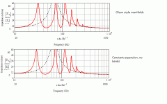
No, quite correct. Welcome to the laws of physics where when mouth size is compromised over the optimal for a given Fo, the acoustic impedance is no longer fully resistive & we're relying more on resonant action. Bends aren't particularly an issue, as you can see from the attached. Top = Saburo horn unfolded, expanding cascade of straight manifolds. Bottom = unfolded horn with same St, Sl & basic flare profile but with continuous expansion. Short of damping them per a TL, this applies to any pipe or 'cone' / expanding pipe with a compromised terminus area. And most are (unless you've room for a horn with a 50ft^2 mouth CSA. Per cabinet).
No, quite correct. Welcome to the laws of physics where when mouth size is compromised over the optimal for a given Fo, the acoustic impedance is no longer fully resistive & we're relying more on resonant action. Bends aren't particularly an issue, as you can see from the attached. Top = Saburo horn unfolded, expanding cascade of straight manifolds. Bottom = unfolded horn with same St, Sl & basic flare profile but with continuous expansion. Short of damping them per a TL, this applies to any pipe or 'cone' / expanding pipe with a compromised terminus area. And most are (unless you've room for a horn with a 50ft^2 mouth CSA. Per cabinet).
Attachments
Last edited:
1. May I ask what tool you used?
The software is Speaker Workshop. I built a Wallin Jig2 for the soundcard interface. I'm just using the SigmaTel audio built into my laptop.
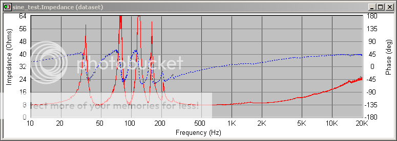
2. Interesting that there are ~5 peaks, and ~5 big bends in the horn.
I was interested by the peaks as well. That's what prompted my post. I don't understand their significance, but I'm trying to wrap my brain around what Scott said. I've measured the impedance curve for a typical ported (bass reflex) enclosure. You get two peaks, presumably one from the woofer and one from the port. I've also measured some aperiodic enclosures (Dynaco A25). They only show one peak.
3. Would it be correct to say that the F3 is ~40hz?
I'm not sure that can be assumed. I don't believe the impedance peak necessarily aligns with the low end cutoff. I've played some test tones, and these guys seem to run out of steam fast below 60~55 Hz. I'm trying to get a test microphone set up, but it is a struggle to get it to work with Speaker Workshop. I think I'll give up and try Arta for a while.
4. How do you like them?
The jury is still out. They are very curious animals indeed.
Last edited:
Depends on the room but F3 will typically be 40 - 45Hz.
Aperiodic boxes are basically (leaky) sealed cabinets, so yes, they will only have a single impedance peak. A BR cabinet should possess two. An expanding pipe will possess a variety depending on length, flare profile, throat & terminus areas unless it is impedance matched down to its design cut-off, i.e. full-sized.
Aperiodic boxes are basically (leaky) sealed cabinets, so yes, they will only have a single impedance peak. A BR cabinet should possess two. An expanding pipe will possess a variety depending on length, flare profile, throat & terminus areas unless it is impedance matched down to its design cut-off, i.e. full-sized.
Fascinating, gentlemen! The Harvey is still one of my all-time favorite speakers (built by Phil Townsend) and I've been curious about the Saburo.
Scott, many thanks. Would it be too simplistic to think that each peak/dip roughly corresponds to the QW resonance of a manifold (not that it necessarily matters in the larger picture)?
Scott, many thanks. Would it be too simplistic to think that each peak/dip roughly corresponds to the QW resonance of a manifold (not that it necessarily matters in the larger picture)?
Only a bad one (as in valve amp). The vast majority of people who have built these cabinets run valve amplifiers to the best of my knowledge, and most have been quite happy with the results. As far as I'm concerned, that's all that matters.
Why the 'real'? They're completely different enclosure types. Your boxes (at least, the ones I assume you are refering to) run twin drivers in a bipolar configuration, each loading a highly compromised damped horn / expanding pipe differentially tuned to fill in the harmonic nulls. Saburo is a large, forward firing bifurcated catenoid horn (somewhat less compromised, though these things are relative) with an MTM style terminus configuration. Trying to compare them is a bit like comparing a snake with a baboon: pointless. Not that it makes much difference given that Saburo is obsolescent.
You will have noticed, I trust, the rather accurate correlation between the graphs posted above?
No problem.
No, it's not got much to do with the manifolds per se; that was the point I was making with the above two graphs. Forget folds for a moment: just assume it's all straightened out i.e. heading in the same direction. Top plot is just that, lower plot is a horn with the same throat & terminus area as Saburo, and the same basic flare profile it approximates, but with continuous (i.e. smooth) expansion. Not much of a difference, right? Most back-horns are not impedance matched down to cut off. They can't be; you need huge mouth sizes to do that, so they rely on resonant action on the bottom end until they reach impedance-matching higher up.
Why the 'real'? They're completely different enclosure types. Your boxes (at least, the ones I assume you are refering to) run twin drivers in a bipolar configuration, each loading a highly compromised damped horn / expanding pipe differentially tuned to fill in the harmonic nulls. Saburo is a large, forward firing bifurcated catenoid horn (somewhat less compromised, though these things are relative) with an MTM style terminus configuration. Trying to compare them is a bit like comparing a snake with a baboon: pointless. Not that it makes much difference given that Saburo is obsolescent.
You will have noticed, I trust, the rather accurate correlation between the graphs posted above?
Scott, many thanks. Would it be too simplistic to think that each peak/dip roughly corresponds to the QW resonance of a manifold (not that it necessarily matters in the larger picture)?
No problem.
No, it's not got much to do with the manifolds per se; that was the point I was making with the above two graphs. Forget folds for a moment: just assume it's all straightened out i.e. heading in the same direction. Top plot is just that, lower plot is a horn with the same throat & terminus area as Saburo, and the same basic flare profile it approximates, but with continuous (i.e. smooth) expansion. Not much of a difference, right? Most back-horns are not impedance matched down to cut off. They can't be; you need huge mouth sizes to do that, so they rely on resonant action on the bottom end until they reach impedance-matching higher up.
Last edited:
Hi Scott, thank you!
I've never seen (or at least noticed) harmonics on an impedance plot, and it looks like that's what is there (e.g., on your top graph, peaks seem to be multiples of ~30, the dips multiples of ~45).
So I gather that "impedance matched" would mean "designed to have a flat impedance" (sorry to be dense)?
Not exactly. As noted above, it is in reference to compromised terminus size. When terminus area of a horn is undersized, as it almost invariably has to be for bass horns, you get a standing wave (supersonic shockwave) reflected back along the horn path. Horns are basically impedance matching devices, viz. matching the high impedance of the diaphram to the low impedance of the air, and thereby improving efficiency as the driver is 'seeing' a constant resistive load at all frequencies in its functional BW. Nominally horn terminus circumference should be a minimum of 1 wavelength of the lowest frequency to be reproduced in order to avoid this; depending on localised SoS for a 40Hz horn you're looking in the order of termini areas of 50ft^2+. More to it than that as you need to consider boundary loadings, whether a particular horn is reactance annulled (back horns usually aren't, although it's technically possible); you also need to be careful in other areas -Keele has demonstrated that beyond a certain mouth size efficiency will begin to drop away.
I was interested by the peaks as well. That's what prompted my post. I don't understand their significance, but I'm trying to wrap my brain around what Scott said. I've measured the impedance curve for a typical ported (bass reflex) enclosure. You get two peaks, presumably one from the woofer and one from the port.
Not quite. Ports actually bring the impedance down, as it (at tuning) loads the driver considerably, resulting in little cone excursion, but lots of output.
When port tuning = driver fs, there are two impedance peaks, approximately an octave above and below, and roughly equal in magnitude.
Driver fs = 33Hz, port tuned to 33Hz Peaks at 17.5Hz, and 61Hz
When port tuning is higher than fs, the lower frequency peak moves to an octave below (ie, further up the hertz) and becomes larger, and the higher peak becomes smaller in magnitude, and moves higher still (though it now appears to be around 1/2 an octave.
Fs = 33Hz, tuning = 50Hz. Peaks at 24 and 70Hz, dip at tuning frequency.
When tuning is below fs, the opposite to the above happens.
Fs = 33Hz, port tuning = 20Hz, impedance peaks at 12 and 56Hz, where the latter is greater in magnitude.
This was done using winISD modelling a generic 8" DVC woofer, always in a 30 litre enclosure.
Chris
Hi Scott, thank you -- understood! I appreciate your help.
Understanding horns is just about the hardest thing I've ever encountered. The problem is once you hear them, you end up ruined and it becomes a years-long obsession. For me, that started with hearing Harvey (instant horn addiction), now I am cobbling together an Azurahorn 160 with a K-Horn. Luckily that can be done without really understanding much
Thank you again for the explanation. You are very generous with your time (and newbies). I've been having fun browsing your new site, by the way.
I've never seen (or at least noticed) harmonics on an impedance plot,
They are evident in any undamped quarter wave resonator
dave
Oops, Dave, you are completely correct. Thank you for the correction. My newbi-ness is never-ending.
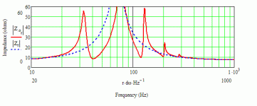
I hadn't personally seen that on MLTL impedance plots but just went back to MJK's BiB article and they are, ahem, hard to miss (top of page 2). MLTL != horn. Thank you again. I think I should just be silent from now on
I hadn't personally seen that on MLTL impedance plots but just went back to MJK's BiB article and they are, ahem, hard to miss (top of page 2). MLTL != horn. Thank you again. I think I should just be silent from now on
Generic driver stuffed into a randomly sized pipe for demo purposes):
MLTL does not = horn. It's an MLTL, viz. an untapered quarter-wave resonator resistively loaded by choking down the terminus area with a slot, port or whatever. What harmonic modes remain are then minimised by placing the driver at x distance from the throat, with the remainder being damped out by appropriately stuffing or lining the pipe.
A horn, at its simplest, may be regarded as simply a pipe that expands toward the terminus.
Attachments
Last edited:
Well I for one learned a lot today! I was not making these connections:
(a) that the impedance could be so closely related to the FR plot (maybe two sides of the same coin even?), and
(b) that a compromised horn acting as QW resonator down low is so similar to a TL with driver offset of zero (der). I have read this over and over but am only just now comprehending.
Thank you Scott and Dave!
Horns are basically impedance matching devices, viz. matching the high impedance of the diaphram to the low impedance of the air, and thereby improving efficiency as the driver is 'seeing' a constant resistive load at all frequencies in its functional BW.
I was just curious if this makes true to some extent the claims from commercial takes on full range drivers that give a higher sensitivity spec for a speaker than the driver it houses. For example (if don't go wrong) the maxxhorn once claiming well over 90db sensitivity from markaudios.
A horn will give you gain at the frequencies it operates thru. In the case of a rear-loaded horn, that means that the horn can lift the bass, but not the range where the driver is acting as a direct radiator. Hence the efficiency, which is determined by the output in the range where the box is a direct radiator, should be close to the actual free air efficiency.
dave
dave
- Status
- This old topic is closed. If you want to reopen this topic, contact a moderator using the "Report Post" button.
- Home
- Loudspeakers
- Full Range
- Impedance plot for Saburo?


