I'm in the process of reusing a pair of Beyma MC115s, the Fs is quite high, measured ~750Hz, so I need to null the resonance bump to use them from ~900Hz or so.
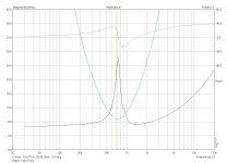
Cobbled together an RLC filter, how does this look? (Blue is the filter, Black is the driver):
Cobbled together an RLC filter, how does this look? (Blue is the filter, Black is the driver):
Attachments
Have you looked at them in parallel? Use the unaltered driver as an overlay to see you don't pull it down further than needed.

For example, increase the inductance until the filter is centred, then increase it a little more and reduce the capacitance until it is centred again, then adjust the resistance.
fortunately, my impecuniosty paid off: My original inductor was a 1.65mH in series with a 0.5mh; shorting out the 0.5mh flattened the driver in parallel with notch curve nicely, now just need to up the R around 1.5 ohms, to see if that improves things any...
There's not really a right or wrong since to get this flat would take more than 3 components, and that's not necessary of course.
Just one possible suggestion.

Just one possible suggestion.
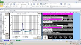
Allen, interestingly, your suggestion is close to what a german site suggested several years ago. I still have that filter, so I'll run that though ARTA & see what it looks like. I think I'll get my HPF together before I do any more tweaks, after all, it's the synergy of the whole shebang that matters..cheers!
Try series crossover - you don't need RLC impedance compensation with it.I'm in the process of reusing a pair of Beyma MC115s, the Fs is quite high, measured ~750Hz, so I need to null the resonance bump to use them from ~900Hz or so.
Cobbled together an RLC filter, how does this look?
GM, fitting an RC only seems to complicate the process, not that flat isn't possible.. I think I'd be seeing what could be done about the high passing before going back to the impedance compensation.
Can you add padding resistors. A 2 ohm, and 10 ohm combination would knock down the spike, and the rise towards 20k.
GM, the german xover had both a notch for the Fs bump & zobel for the HF
Sonce, great idea, that had been in the back of my mind, I'll think about it after the seasons excesses are dealt with
temp25, there will be padding, I may even make it switchable for a couple of options
Sonce, great idea, that had been in the back of my mind, I'll think about it after the seasons excesses are dealt with
temp25, there will be padding, I may even make it switchable for a couple of options
Keep in mind the impedance flattening circuits are there to serve the frequency response, not the filters per se. Sometimes a little combination of nudging both is a good solution
Understood; again, just curious WRT ya'll's preferred impedance compensation as a side issue for my edification since at this late date not interested in learning any new programs.GM, fitting an RC only seems to complicate the process, not that flat isn't possible.. I think I'd be seeing what could be done about the high passing before going back to the impedance compensation.
Sure. I can only speak for myself but first thoughts are that the function behind the peak is difficult for a versatile high pass filter to modify so I see that as worth handling on it's own. The bumps are probably too small to prioritise and the rise is a simple function so it's not so much on the radar. IMHO.
OK, since I prefer the pioneer's 1st order w/wide range horns, IC was foremost, though they did it in the electronics.
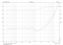
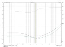
Here's a before and after impedance that results from using two resistors for padding. A 10 ohm, and 2 ohm. The 10 ohm is across the driver terminals, and the 2 ohm is in series.
If the 2 ohm is increased to 5 ohms, the padding amount is increased, and the green line simply moves up another 3 ohms.
If the 2 ohm is increased to 5 ohms, the padding amount is increased, and the green line simply moves up another 3 ohms.
Attachments
- Home
- Loudspeakers
- Multi-Way
- Impedance nulling filter