I'm trying to bypass the buffer stage of NCx500 to get a lower gain @11.5dB (also getting better SINAD). But if I do that the input impedance of NCx500 becomes to be 1.5k Ohm. My source is a Motu Ultralite MK5, which has a output impedance of 220 ohm. It doesn't seem to perform optimally when matching with low input impedamce amps. Can I just make an attenuator and match their impedance better? Will there be a loss in terms of frequency response? Thanks in advance!
You don't match impedance with solid state audio, you drive high impedance from a low impedance for minimum voltage droop. A separate attenuator is the way to go, keep the NCx500's original 47k input impedance and a 5k or 10k preset-pot or volume pot should work. Expect any modern solid state preamp/source to be able to drive 2k or higher fine (since most opamps are designed for 2k load).
And you don't have to worry about frequency response either really - that's only as issue with high output impedances and long cables.
And you don't have to worry about frequency response either really - that's only as issue with high output impedances and long cables.
Without a schematic, you should assume a Motu minimum load of 10k for best low frequency response.
So for the attenuator use a series 10k, and a shunt resistance that gives you the needed loss.
The shunt resistor is also paralleled with the NCx500 1.5k input impedance, so include that
in your calculation.
So for the attenuator use a series 10k, and a shunt resistance that gives you the needed loss.
The shunt resistor is also paralleled with the NCx500 1.5k input impedance, so include that
in your calculation.
Last edited:
Thank you for the insight guys. I’m still pretty confused about impedance matching of u-pad attenuator here.
I understand that we typically don’t need to match impedance any more in modern audio gears as long as output impedance of DAC and input impedance of Amp is at least a ratio of 1:10.
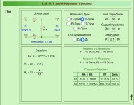
But I’m confused about what input/output impedance I should set for the u-pad attenuator. I see there are calculators online that provides this type of calculation: https://k7mem.com/Res_Attenuator.html
And it looks like I can either match impedance towards input(Z1) or output(Z2) impedance. I did some search but still can’t understand which way should I match the impedance.
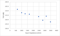
The motu’s output impedance is 220 ohm and I saw an experienced user measured the THD giving different load using e1da ADC on ASR. It looks like 1.5k ohm will not be an optimal input impedance for motu. So should I just leave the AMP’s buffer stage there so that the input impedance is 47k ohm?
I understand that we typically don’t need to match impedance any more in modern audio gears as long as output impedance of DAC and input impedance of Amp is at least a ratio of 1:10.
But I’m confused about what input/output impedance I should set for the u-pad attenuator. I see there are calculators online that provides this type of calculation: https://k7mem.com/Res_Attenuator.html
And it looks like I can either match impedance towards input(Z1) or output(Z2) impedance. I did some search but still can’t understand which way should I match the impedance.
The motu’s output impedance is 220 ohm and I saw an experienced user measured the THD giving different load using e1da ADC on ASR. It looks like 1.5k ohm will not be an optimal input impedance for motu. So should I just leave the AMP’s buffer stage there so that the input impedance is 47k ohm?
Attachments

If you're going to lower your power amplifier voltage gain all the way down to 11.5db you DON"T want an attenuator between source and amplifier. 🙂
What the heck is wrong with the SINAD of the NC amplifier using the input gain stage (it's not a buffer stage) as-designed???????????????
And, as mentioned by the guys above, your query has zero to do with impedance matching.
Dave.
What the heck is wrong with the SINAD of the NC amplifier using the input gain stage (it's not a buffer stage) as-designed???????????????
And, as mentioned by the guys above, your query has zero to do with impedance matching.
Dave.
So consider the amp as another resistor. Regardless of what value of the shunt resistor, the paralleled total resistor value will be lower. So the motu will behave even worse? Is that why I want to keep the buffer stage of the amp so that the input impedance is 47k ohm. The gain will be 20dB in total, then I should just build an attenuator and lower it to the desired gain?
Attachments

"Impedance matching" maters for high frequency transmission lines where reflections are possible, or where you need to extract the maximum possible power output, or where you are loading or driving a reactive network, which some may argue includes loudspeakers. But unless transformers are involved, amplifiers inputs and outputs do not have such problems. Typically, an output produces the least distortion when unloaded, ie infinite impedance, and an input produces the widest frequency response and least noise when driven by a voltage source, ie zero impedance. Provided you choose rational loading and source impedances, your objective should be to match the interstage dynamic range so that all stages are well above the noise floor and well below clipping.

Impedance matching is done in RF to preserve precious low signal levels, or prevent stuff from burning up, roughly speaking.
In audio it is not an issue at all. If your source impedance is stated as 200 Ohm, you can for the most part ignore this unless you are running hundreds of feet of wires and need to keep a low impedance system for minimizing interference, signal delays and reflections. The "200" number is just a capability number, like hp of en engine, which is not typically challenged with a constant load. You can load it with anything above 200, like 5k, 10K, etc etc. Not critical.
10dB is ten times, a 9k and a 1k resistive voltage divider would do that.
Actually, 10dB is a 10:1 power ratio, which is a 3.16:1 voltage ratio , so it needs about 2k2 and 1K, or two 1k1 and a 1K for balanced. Three 1K (etc) resistors is 3:1 or 9.5dB. Impedance mater to RF because RF wavelengths are short enough to cause standing waves on cables less than a mile long.
But Davey is right: the power amp should have a gain pot to do this.
But Davey is right: the power amp should have a gain pot to do this.
So consider the amp as another resistor. Regardless of what value of the shunt resistor, the paralleled total resistor value will be lower. So the motu will behave even worse? Is that why I want to keep the buffer stage of the amp so that the input impedance is 47k ohm. The gain will be 20dB in total, then I should just build an attenuator and lower it to the desired gain?
The series attenuator resistor is chosen to be equal to, or greater than, the Motu minimum load.
It is completely safe to choose the series resistor equal to 10k.
Without more detailed information, it should not be chosen to be lower.
Impedance matching is not at all relevant here, please disregard that notion entirely.
The reason I want to add an analog u-pad attenuator is because the sound card is connect to two amps of different gain. One with 9.4dB, one with 20dB. I can do 10dB digital attenuation but since I only have a digital volume control and I usually set the volume at -30dB, this adds up to 40dB digital attenuation in total. So I’m thinking that analog attenuator will perform slightly better.
Impedance matching is not important but every u-pad calculator online is asking me to type in a value for input/output(Z1/Z2) impedance to calculate the series and the shunt resistor values. According to the online calculator, when attenuate 10dB, K is around 3.16, then series resistor value=Z2*(K-1).
Impedance matching is not important but every u-pad calculator online is asking me to type in a value for input/output(Z1/Z2) impedance to calculate the series and the shunt resistor values. According to the online calculator, when attenuate 10dB, K is around 3.16, then series resistor value=Z2*(K-1).
yep, you are right, got lost in the RF space. 20 log, not 10.Actually, 10dB is a 10:1 power ratio, which is a 3.16:1 voltage ratio , so it needs about 2k2 and 1K, or two 1k1 and a 1K for balanced. Three 1K (etc) resistors is 3:1 or 9.5dB. Impedance mater to RF because RF wavelengths are short enough to cause standing waves on cables less than a mile long.
But Davey is right: the power amp should have a gain pot to do this.
I hate putting pots on power amps, some intermediate equipment, mixer console, preamp, whatnot, should go between signal source and power amp. If the source is digital, the equipment is theoretically able to control signal levels, but thats up to the implementation. A regular pot would also attenuate the noise of the source, which may be better than losing bit depth.
Forget about those. Why put resistance in the ground lead anyway? You need not worry about source- and load impedance's as long as you keep the attenuators value well above what the source can supply without strain.u-pad calculator
A 2K pot would do fine with a 200 Ohm source (capability), or 10K, even 25K or 50K are also OK.
Those Alps are OK, am a zon, e B ay etc
I’m thinking about soldering the resistors inside the XLR terminals so that it looks more elegant…Why put resistance in the ground lead anyway?
The motu is 220ohm output impedance. So if I want to have 10dB attenuation, it would be 20*log_10(3.16)=10. So as long as R_shunt🙁R_series+R_shunt)=1:3, it would be good? In a u-pad, suppose R_series=2k2, then R_shunt is about 1k, R_series 1/2 is then 1k1 ohm. Is my calculation right?
The actual resistance values are irrelevant as long as they are higher than the source impedance, the ratio between them is important. Those values will work. Why not use a potentiometer? Forget about the U-pad.
Thank you for confirmation of my calculation. I have more than 4 channels, so I will have to add quite a few pots. I think attenuators make sense here if they do not deteriorate the sound and they are small enough to fit inside the XLR terminals.The actual resistance values are irrelevant as long as they are higher than the source impedance, the ratio between them is important. Those values will work. Why not use a potentiometer? Forget about the U-pad.
I understand impedance matching are only for RF applications and for audio they are not necessary. But input/ouput impedance still matters in the sense that input😱utput impedance ratio should be at least be 1:10 right? Someone measured motu with different load with e1da ADC and it looks like it performs the best with 4k ohm.
So, suppose the series resistors are 1.1k and shunt is 1k, to calculate the input impedance the motu sees, it’s basically (47kohm || 1k)+2.2k right? Which is about 3.2kohm. This is more than 10 times 220ohm. So it should be fine for the motu. But for optimality, 3.5k ohm would be better right?
The opposite direction. For the Amp, the output impedance it sees is (220ohm+2.2k ohm) || 1k ohm, which is about 3k ohm. Less than 1/10 of the input impedance of the amp.
Attachments
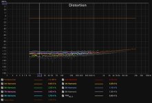
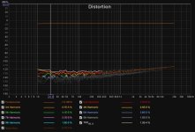
I tested with cheap 1% resistors. Two 1.2k series ressitors and one 1k parallel resistor, soldered to the XLR terminal. The test is done using motu's Line Out 7(TRS out) connected to Mic In 1(XLR in). Main volume of motu is set to -14dB since 0dB will cause the Mic in to clip. The attenuation is about -12dB, more than expected. Not sure why. But I guess the distortion graph comparing analog and digital volume makes sense?
Attachments
- Home
- Source & Line
- Analog Line Level
- Impedance Match Question