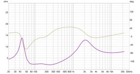
This is an impedance graph of my DIY 3 way build.
Two Satori WO24P (8 ohm nominal) woofers in parallel
One Scanspeak 18M 4531 Mid Range
One Wavecore TW030WA11 Tweeter
The final Crossover is all 2nd order stuff. But the impedance graph is a bit concerning. I use Class D Ncore and Purifi amplifiers which are rated for 2 ohms. The load dips to 2 ohms between 200 and 300Hz. It also dips to 2.4 ohms between 75 and 200Hz. Otherwise it looks clean. How concerned should I be?
Attachments
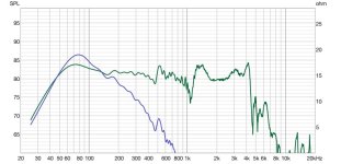
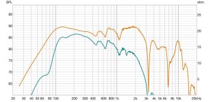
While the amps can probably handle the load without issue, the more salient point is typically whether the crossover is worsening the load unnecessarily. Comparing the raw impedance of the woofers in parallel (with no crossover or other drivers connected in the model) to that of the final impedance of your design may help point out areas that might deserve some attention.

May be worth thecking the current going into the passive components in the mid bass filter. They may overheat of a lot of watts are to be dissipated
So play as loud as you will use them and check temperature after ato minutes or when a burning smell emerges
As an amplifier designer type guy, my concern with your impedance plot is the 2 ohm region is very wide and flat right in the region where there is a lot of music energy ie 70 Hz through to 300 or 400 Hz. If I’m reading the graph correctly the phase angle is about -45 deg through to 0 deg over that region, so luckily not too bad. If you could get the minimum Z above 3 ohms (3.5 would bd great), I’d say that would be better.
Would you show the woofer and mid responses with and without the crossover, and the crossover itself..
4 ohm bass and 4 ohm midrange with a large overlap 12dB filter may make it hard to keep the impedance high enough. Maybe try 24dB with less overlap or an 8 ohm midrange driver?
Impedance often rises around a crossover. I was more interested in seeing the effect of the filters on the individual driver responses.
Both brands have a wide range of power, and current limiting at 2 ohms.I use Class D Ncore and Purifi amplifiers which are rated for 2 ohms.
There would be a difference between running a 2000 watt amp at 200 watts and a 200 watt amp at 200 watts.
That said, as long as the amp is not running hot, I would not be concerned running an amp rated for two ohms at two ohms between 75 and 300 Hz where dynamic range would generally result in less than 10% of peak power used.
OK. Here's your answers. Have at it.Would you show the woofer and mid responses with and without the crossover, and the crossover itself..
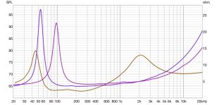
Notes: These are near-field measurements. The woofers are a measurement of one woofer but there are 2. I apologize for the crude diagram of the crossover but I don't use any simulation software so I just threw it together. Woofers are a simple 2nd order. Mid is 2nd order high pass, baffle step circuit then 2nd order low pass.
Attachments
This is what I'm concerned about. I can't switch to an 8 ohm woofer without costing myself a lot of money. I'm hoping to fix it in the crossover. Using 4th order slopes is not out of the question.4 ohm bass and 4 ohm midrange with a large overlap 12dB filter may make it hard to keep the impedance high enough. Maybe try 24dB with less overlap or an 8 ohm midrange driver?
Yeah, do you have any suggestions on how to do that without a massacre to my frequency response (which is really good t this point).As an amplifier designer type guy, my concern with your impedance plot is the 2 ohm region is very wide and flat right in the region where there is a lot of music energy ie 70 Hz through to 300 or 400 Hz. If I’m reading the graph correctly the phase angle is about -45 deg through to 0 deg over that region, so luckily not too bad. If you could get the minimum Z above 3 ohms (3.5 would bd great), I’d say that would be better.
See my other post that has this graph and let me know what you think. Thanks to you and everyone for the help and insight on this.While the amps can probably handle the load without issue, the more salient point is typically whether the crossover is worsening the load unnecessarily. Comparing the raw impedance of the woofers in parallel (with no crossover or other drivers connected in the model) to that of the final impedance of your design may help point out areas that might deserve some attention.
Is this what you mean for the midrange circuit? This model isn't using real driver impedance - just a flat 4 ohms instead.

Last edited:
I'm hoping that I did this right, but here they are. I think.Would you be willing to post the FRD and ZMA files for these two?
Attachments
No, the C2 is after the L3 (closer to the driver). This is the 2nd order low pass circuit.Is this what you mean for the midrange circuit? This model isn't using real driver impedance - just a flat 4 ohms instead.
View attachment 1392267
Sorry. Try to do a crossover with some serious simulation. Just throwing something together gives exactly what you have got. If you like the sound and frequency response for some reason, leave it as it is. Your amp should handle it, your ears may suffer...I apologize for the crude diagram of the crossover but I don't use any simulation software so I just threw it together.
C2 is after the L3 (closer to the driver)
OK, that's where it should be. I just wasn't sure where you had it given what was in your PDF.
Your midrange circuit seems to be pulling impedance down around 200 Hz. That can likely be improved.
Stating where your cross points were intended to be and how much baffle step compensation you were aiming for may help those who want to model it for you.
- Home
- Loudspeakers
- Multi-Way
- Impedance graph-How concerned should I be about a 2 ohm load?