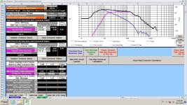
I can't get your files to play nice, but try something like this. Obviously it will need adjusting, but who knows. The .82mH was a random value while I was using the scroll wheel. If you really want to cross the tweeter lower, this would be larger. My sim showed a minimum of 4 ohms.
Attachments
Last edited:
Crossover points would ideally be at 200Hz between the woofers and mid-range. Baffle compensation needs to be about 4d from what I see in measurements.View attachment 1392340
OK, that's where it should be. I just wasn't sure where you had it given what was in your PDF.
Your midrange circuit seems to be pulling impedance down around 200 Hz. That can likely be improved.
Stating where your cross points were intended to be and how much baffle step compensation you were aiming for may help those who want to model it for you.
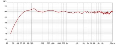
This is the frequency response that I have. It wasn't thrown together. It was done with measurements and sounds quite nice. The off-axis measurements show a very effective downward slope. Just because I don't use simulation software, it doesn't mean I don't know what I'm doing. My ears are certainly not suffering.Sorry. Try to do a crossover with some serious simulation. Just throwing something together gives exactly what you have got. If you like the sound and frequency response for some reason, leave it as it is. Your amp should handle it, your ears may suffer...
Attachments
I didn't use your response files but that doesn't make a difference to what I'm about to say since it's the relative difference that matters.
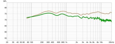
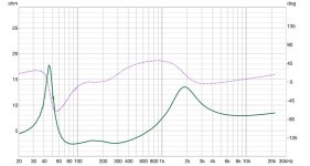
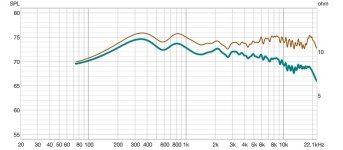
First plot is the woofer, with and without crossover comparison of impedance and response. You can see the impedance drops where you've used resonance to increase the response above the ordinary level.
The mid plots show the high pass filter section is not well damped by the impedance to the right of it.
I'm sorry to sound like 'a broken record' but if you have the right amplifier with high current capacity, you don't even need to worry about 2 ohms.
This is one reason that I like my power amplifier so much 🙂
This is one reason that I like my power amplifier so much 🙂
Yeah, I saw all of that. I'm not purposely increasing the level of the woofers with that resonance. It just seems to happen no matter what I do with the slope of the crossover. It's especially bad when I use a low DCR inductor. I tried several different methods to ease this but still get the slope that I wanted and it eluded me so I settled with what I had since it yielded an overall excellent response.I didn't use your response files but that doesn't make a difference to what I'm about to say since it's the relative difference that matters.
First plot is the woofer, with and without crossover comparison of impedance and response. You can see the impedance drops where you've used resonance to increase the response above the ordinary level.
The mid plots show the high pass filter section is not well damped by the impedance to the right of it.
View attachment 1392374
View attachment 1392375
The mid woofer was also a struggle to get the slope correct. It's very easy to do with an active filter but getting the same slope with passive components again eluded me. At this point, I'm going to try some other options with steeper slopes on them to see if I can maintain a good frequency response and get that impedance closer to 3 or 3.5 ohms. If not, then I think my amp will be fine and if it burns up then I will put out the fire and a very important lesson will be learned. Thanks for looking at this for me.
You're very close to their resonance impedance peaks. The phase variation makes these a tricky load. You could try trimming them with a RLC compensation circuit. That might go a small way to easing those issues.
Sorry, speaker design is a black art to me. There’s lots of experts on the forum though 😊Yeah, do you have any suggestions on how to do that without a massacre to my frequency response (which is really good t this point).

Your 22.5" CTC of woofer to mid is good with any xover point BELOW 600 Hz. Try a higher xover point than 200Hz, and it will get easier.
At 200Hz you won’t be bothered by floor bounces either. Mounting one of them higher and nearer to the mid wil mitigate further floor bounce effects.
This design needs to be redone to become an easier load to the amplifier. Midrange LP circuit needs improvement also.
Where is the rest of the filter?
Where is the rest of the filter?
Can you explain to me how you came up with 600Hz for the 22.5" value?Your 22.5" CTC of woofer to mid is good with any xover point BELOW 600 Hz. Try a higher xover point than 200Hz, and it will get easier.
I'd like to sim this if you get files that work. It looks like your posted mid response is going much lower than 200hz. I suggest trying a smaller cap than 200uf.Yeah, I saw all of that. I'm not purposely increasing the level of the woofers with that resonance. It just seems to happen no matter what I do with the slope of the crossover. It's especially bad when I use a low DCR inductor. I tried several different methods to ease this but still get the slope that I wanted and it eluded me so I settled with what I had since it yielded an overall excellent response.
The mid woofer was also a struggle to get the slope correct. It's very easy to do with an active filter but getting the same slope with passive components again eluded me. At this point, I'm going to try some other options with steeper slopes on them to see if I can maintain a good frequency response and get that impedance closer to 3 or 3.5 ohms. If not, then I think my amp will be fine and if it burns up then I will put out the fire and a very important lesson will be learned. Thanks for looking at this for me.
I was able to get those files into VituixCad. I just don't really know how to use that program very well.Did the posted files work for anyone?
When I opened the files, it was a full width page of gibberish, instead of several columns of numbers.
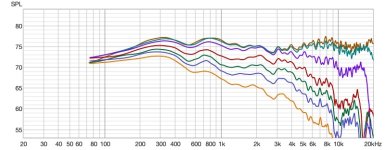
Alright. I worked on this all day. First I changed the woofers to a 4th order and the mid to a 3rd order because that's what kept them in phase and the impedance got worse. Then I went back and just revised the 2nd order crossover and got it to be a minimum of 2.5ohms. To me, the real flaw in the design is trying to put these woofers in parallel, especially with a 4 ohm mid-range. Lesson learned but since they're built I wanted to make the best of them. On-axis response is about +/- 1.5db for almost all of it and the off-axis average is a really good downward slope. They sound great and I will be using a Buckeye Class D amplifier for them so the impedance load should be fine. Thanks to everyone for the advice on this!!
Attachments
- Home
- Loudspeakers
- Multi-Way
- Impedance graph-How concerned should I be about a 2 ohm load?