I am using the jackinnj PCB from tech-diy.com. The grid stoppers are 1k metal film. The current source gate stoppers are 120R metal film.You may need to look at the position/value of the grid and gate stoppers.
The voltage and noise measurements look good. The THD measurements are considerable higher than presented in the AudioExpress article, probably due to the particular electro-harmonix tubes I am using.
I have been using the Impasse for many days now, and I haven't noticed the particular "abnormal" transient response since early listening tests.
I forgot to mention: My ImPasse is driven single-ended (no input transformers) with 3 foot RCA cables from a Buffalo-IIISE DAC. The plate output cap is shorted to ground, and the single-ended cathode-follower output drives about 3 feet of RCA cable to my F4.
Overall, the preamp sounds very good.
Overall, the preamp sounds very good.
Hi,
This is my first tube project and building my own power traffo for Impasse.
I was wondering why 6K3VG traffo choosen is 650Vac if all you need prior to regulator is 400Vdc,
650Vac / 1.414 = 459 - 1.5 (diode drop) = 458
If 400Vdc raw supply prior to regulator, where is this 59V needed for?
If I'm using Salas HV reg which need only 20Vdc (20mA) drop to regulator, can a 526Vac secondary be possible so that (526/1.414 ) - 1.5 - regulator drop = 350Vdc ?
Thanks!
Last edited:
It was the closest, cheap, off the shelf transformer I could get on short notice. There's nothing critical or special about it. As you perceived, the main thing is to get enough voltage to the regulator to allow it to work; how that happens isn't particularly important- the regulator sets the quality of the DC rail.
Thanks for reply and sharing the Impasse SY.
I can save the extra winding for heater then.
I find Impasse simple for first time tube project... and nice sounding (I hope)😉
I can save the extra winding for heater then.
I find Impasse simple for first time tube project... and nice sounding (I hope)😉
Hi,
This is my first tube project and building my own power traffo for Impasse.
I was wondering why 6K3VG traffo choosen is 650Vac if all you need prior to regulator is 400Vdc,
650Vac / 1.414 = 459 - 1.5 (diode drop) = 458
If 400Vdc raw supply prior to regulator, where is this 59V needed for?
If I'm using Salas HV reg which need only 20Vdc (20mA) drop to regulator, can a 526Vac secondary be possible so that (526/1.414 ) - 1.5 - regulator drop = 350Vdc ?
Thanks!
it is easy to lose some volts by dropping resistor, rather than not have enough.....
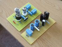
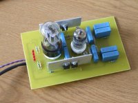
Ready for testing
Well after careful checking of the PCB I did find one small omission. HT(L) and HT(R) weren't connected together.
Not a problem, I've just linked them under the board.
Bowing to the experience of others I have also added a bit of heatsinking to the CCS MOS-FETs.
I'm still waiting for the chassis to arrive to put it together and test it.
Attachments
Magic Smoke !!!
A little bit of magic smoke ???
Not using the impasse itself but loading the PSU with a 10K 20W resistor it looks as though R105 has gone up in smoke.
Could that be because I'm using a 10K load ?
I've checked the PCB and everything seems OK.
A little bit of magic smoke ???
Not using the impasse itself but loading the PSU with a 10K 20W resistor it looks as though R105 has gone up in smoke.
Could that be because I'm using a 10K load ?
I've checked the PCB and everything seems OK.
Do you have insulators between your DN2540s and the heatsinks?A little bit of magic smoke ???
Not using the impasse itself but loading the PSU with a 10K 20W resistor it looks as though R105 has gone up in smoke.
Could that be because I'm using a 10K load ?
I've checked the PCB and everything seems OK.
R105 biases the pass transistor, i've never seen one burn up. it's usually R108 folks have fried
R105 biases the pass transistor, i've never seen one burn up. it's usually R108 folks have fried
That's why I'm questioning if the 10K load is too much ?
I don't know how much difference it makes, I'm using a TIP50 not a TIP50A.
Last edited:
R105 was indeed burnt, caused by a bad track on the PCB. It's all working now regulating nicely at about 335V DC.
It's difficult to describe where the break was but effectively the pass transistor Q101 and IC1 weren't doing anything, the output current was being pulled through R105 and D103. My output voltage seems a bit shy of +350V but I am testing it at 35mA. I'm measuring 335V.
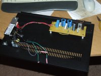
The Impasse is coming together
After the little hiccup above the build is now progressing. The second transformer hiding behind the Allied 6K3VG is just a 240V to 110V transformer because we in England use mans voltage. I had to disrobe the Allied transformer and mount it sideways to fit it inside the 2U case.
After the little hiccup above the build is now progressing. The second transformer hiding behind the Allied 6K3VG is just a 240V to 110V transformer because we in England use mans voltage. I had to disrobe the Allied transformer and mount it sideways to fit it inside the 2U case.
Attachments
Last edited:
Check R108 and R109. The voltage you're getting is only a few percent off, and if those resistors are each (say) 2% in opposite directions, you could easily see a variation like that.
- Home
- Amplifiers
- Pass Labs
- ImPasse Preamplifier