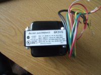
How about this one? It has 2 x 320V and even though it is rated at 50VA, it seems to be enough for the ImPasse.
Antek - AS-05T320
That should be a 1:1 drop in. It's got plenty of safety margin in terms of current delivery.
Have you though about going down the Audio SMPS route. I say Audio with tongue in cheek.
A well filtered SMPS might fit your bill.
I want to build it as Stuart designed it. I have already purchased the boards and about 70% of the components needed.
I agree with you. I'm trying to keep as close to the original design as possible.
I wont be using the input transformers initially as I'm driving it with a B1 buffer amp, the interconnects will be VERY short, the B1 will be taking care of any problems with the source components.
I wont be using the input transformers initially as I'm driving it with a B1 buffer amp, the interconnects will be VERY short, the B1 will be taking care of any problems with the source components.
I still can't figure out how to get R11 and R12 within 0.1% of each other.
My DMM refuses to co-operate. It's only accurate to 2 decimal places.
I thought I was being clever by paralleling the 15K's with a 4K7 for measuring purposes thinking that the DMM would reveal a third decimal place, no, it's only good for two DPs.
My DMM refuses to co-operate. It's only accurate to 2 decimal places.
I thought I was being clever by paralleling the 15K's with a 4K7 for measuring purposes thinking that the DMM would reveal a third decimal place, no, it's only good for two DPs.
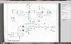
Sy, did I read somewhere that the Source and Drain connections on the original schematic are interposed ?
i.e. Should Source be connected to +ve and Drain to -ve ?
I'm just testing for R4 using the original schematic and I'm getting non-sensical results.
i.e. Should Source be connected to +ve and Drain to -ve ?
I'm just testing for R4 using the original schematic and I'm getting non-sensical results.
Source and drain are fine in the schematic. I screwed up and forgot to change the p-channel symbol to the n-channel symbol.
Matching doesn't require accuracy, only good precision. So if a resistor's value is actually 14992 and the meter says 15056. that's OK because any other resistor reading 15056 will be matched to the first one.
Matching doesn't require accuracy, only good precision. So if a resistor's value is actually 14992 and the meter says 15056. that's OK because any other resistor reading 15056 will be matched to the first one.
My turn to put the dunces hat on ..... Doooooh......
My test rig for the FETs works better if I connect +ve to +ve and -ve to -ve.
Anyway, very surprisingly I bought only 4 x 2540 FETs.
The first pair measured 6.11V across my 814R R4 = 7.506mA, the second pair 6.12V across the same resistor in the same rig = 7.518mA.
I guess that that is a close enough match ?
Am I correct in assuming that 12K5 is OK or do I need to increase it slightly to 13K.
I haven't looked yet to see what 3W values are available.
There is only a limited choice of 2W 1% resistors on E-Bay. I'm loathe to pay the exhorbitant fees for a small order to one of the big suppliers.
Am I correct in thinking that as long as the currents are matched (as mine seem to be) and both R4(L) and R4(R) are both 1% resistors, both channels will be behaving the same so 12K 2W 1% will be OK in both sides.
Oh, by the way, after a bit of pressure, Allied Transformers are refunding me 50% of my postage. And for the guy who was told that they are out of stock, mine was shipped yesterday.
Last edited:
Well, thanks for all the comments about the choice of R4.
If I am correct in assuming that SY was running the CCS at 8mA and wanted to use 12K5, then the volt drop across R4 is 100V.
Transposing Ohms law gives me 13K3 at 7.5mA.
As I can't find 13K3 1% 2W resistors, I'm going to use 4 x 13K3 1% 0.6W in series parallel to achieve the same result.
If I am correct in assuming that SY was running the CCS at 8mA and wanted to use 12K5, then the volt drop across R4 is 100V.
Transposing Ohms law gives me 13K3 at 7.5mA.
As I can't find 13K3 1% 2W resistors, I'm going to use 4 x 13K3 1% 0.6W in series parallel to achieve the same result.
Yes, get the currents reasonably close between channels (within 1mA is fine). The idea of my jig was not so much to match FETs as to indicate the right source resistor for that particular lot to give nominally 8mA.
Cheers Sy. I've solved the problem of 0.1% 15K resistors, I just bought a handful of 0.1% resistors.
There's a Triad R 29A transformer for sale on the 'Bay -- you'll have to use a full wave bridge rectifier instead of half-wave. the filament winding is center-tapped.
As would an edcor including shipping even if it where a custom one . I would opt for the Sowter where you are.
Too many beers and too much haste. Mouser stock them, looking at the delivery time they probably import to order but at a fraction of the cost (eg £60).
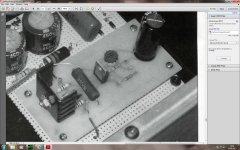
Now for the serious art of building the Impasse
Gents, could you please peruse over my proposed layout of the Impasse PSU PCB to see if I have made any stupid errors or any possible improvements.
The copper is in RED. The Q101/IC1 Heatsink is in GREEN. The silkscreen is in YELLOW.
Gents, could you please peruse over my proposed layout of the Impasse PSU PCB to see if I have made any stupid errors or any possible improvements.
The copper is in RED. The Q101/IC1 Heatsink is in GREEN. The silkscreen is in YELLOW.
Attachments
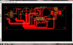
Make sure the heat sink is big enough, considering you are going to place both devices on the single 'sink...
Other than that I like it!
Other than that I like it!
6L6 in the original article only one device, I'm not sure which, was on a smaller heatsink. So the heatsink should be adequate. I've got them sharing the same sink so that any rise in temp will trigger the LM317s temperature limiting.
Attachments
Last edited:
- Home
- Amplifiers
- Pass Labs
- ImPasse Preamplifier