Jack:
Here are my suggestions. Please take them with a grain of salt 🙂 I'd be glad to run a single board prototype once you're done, as I can do this pretty cost effectively. Some of this is hard to describe, so I did my best. I'm sure it's pretty confusing though ...
C3,C4,C7,C8
Auricap 0.47uF/400V 0.60"D x 0.78"L axial cap, with 18awg stranded leads
- same width as current output caps and the existing outer most holes could be
utilized as the current footprint also nicely accommodates the length,
but these holes need to be enlarged to accommodate 18awg wire. It would be nice to add holes so that
nylon ties could be used to secure the caps to the boards. One idea would be to add two
holes that are bisected by the outline of the larger cap footprint and are aligned with
the midpoint of the cap in the other dimension. A single hole between C7,C8 could be used
to pass two cable ties through, assuming it was large enough. This arrangement should not
impede the use of box caps here, or the use of the PAS mounting holes.
C2,C5,C6,C9
Auricap 0.10uF/400V 0.42"D x 0.54"L axial cap, with 18 awg stranded leads
- oh so slightly wider than current caps, but will definitely fit. While the length is less than
the current capacitor pitch, I'd recommend adding another set of pads a bit further out
to accommodate the Auricaps. For C6, C2 I'd just add the pads as close to the GND traces
that connect to C5, C9 and the other pads in the center of the board, right next to each
other. Basically, just put them as far apart as possible. For C5,C9 perhaps you could
move the Vcc1,Vcc2,Gnd1,Gnd2 pads towards the edge of the board, and place them
~5mm apart so a PCB connector (for example, Mouser 651-1733415)
could be used here. If you do this, then you can free up enough room to extend the pitch
of C5,C9. You could even move the caps a bit more towards the center of the board to get
more room for the PCB connector. Also, add the nylon tie holes in similar location to the output caps.
6DJ8
- add jumper to pin that goes to ground so 12.6V heater tubes can use this pin (i.e. prevent
this pin going to ground. Something like a 0.1" jumper block would be nice so it's easily
changable).
Input Transformers
- add 3/8" diameter hole in the center so that the bushing mount transformers can also be used.
In addition, you could add two #4 diameter holes 0.70" apart on center (line connecting the
two would be parallel to the two lines of PCB pins) and this would accommodate the third version
of both the Cinemag and Sowter transformers, and this would be an easy addition.
Resistor Pitch
- R3,R27 (1K series input resistors) increase pitch to same size as R8 (0.6" pitch?)
- R11-R12,R25-R26 (phase spitter plate resistors) increase pitch to same size as
R4 (input plate resistor), should be no problem to do. These two changes should
accommodate most boutique resistors, as the other resistor locations can
already accommodate PRP, Caddock, etc. quite nicely.
Mounting Hole
- Perhaps add one in the center of the board, or even under the 6DJ8 tube socket to help with tube insertion force, as this is a largish board.
Thanks Jack!
jackinnj said:and, if you have to order NE-2's -- they come in assorted flavors -- the NE2H is "leaded", the NE2B is "socketed".
another difference I see is the maximum breakdown voltage, or strike voltage. There seem to be two kinds, 65 VAC (90 VDC) and 95 VAC (135 VDC). Then these can be broken down by "series resistor" (540K, 220K, 150K, 120K, 100K, 68K) even further. I'm assuming the latter is just a recommendation to get specified brightness. The former seems that it might be important to get the higher rating, but what do I know. Any opinions?
luvdunhill said:
another difference I see is the maximum breakdown voltage, or strike voltage. There seem to be two kinds, 65 VAC (90 VDC) and 95 VAC (135 VDC). Then these can be broken down by "series resistor" (540K, 220K, 150K, 120K, 100K, 68K) even further. I'm assuming the latter is just a recommendation to get specified brightness. The former seems that it might be important to get the higher rating, but what do I know. Any opinions?
I just bought a pack of them from Mouser -- the Ne2H variety.
Ne2H -- I thought neon was inert?
Variac said:
-And for those concerned about the Cinemag PC transformers, I understand that they work fine if mounted under the board?
Mark
Is this a "yes", i.e no need to cut any trace if the transformers are mount from below?
Thanks,
SY said:Yes, it will do both equally well, one of the reasons I used it. In my build, I have both XLR for balanced and RCA for unbalanced.
So, where on the schematic do you recommend connecting pin 1 of the XLR inputs? I think I really only need 2 switched inputs (one balanced, and one unbalanced) and am thinking of using a 4PDT toggle switch to do this, but I'm unsure if I really need to switch pin 1 of the XLR, hence the question.
Ideally, you would switch both pins. I blushingly admit I didn't, not having a 4 pole switch on hand.
SY said:Ideally, you would switch both pins. I blushingly admit I didn't, not having a 4 pole switch on hand.
rats, that means I need a 6 pole switch then, probably 5 pole at minimum. Where did you connect pin 1 of the XLR, to signal ground, or to earth?
Sorry I was unclear. The shield of the balanced connector is tied to chassis. The "return" ought to be switched along with the "send" but I sloppily didn't do that. So you still only need a 4 pole switch.
luvdunhill said:
rats, that means I need a 6 pole switch then, probably 5 pole at minimum. Where did you connect pin 1 of the XLR, to signal ground, or to earth?
Time to learn how to deploy a Vactrol or Silonex LDR.
In fact, I am thinking that in the process of resurrecting equipment with dirty phenolic switches the best route would be to use the extant switch to just control the LED on an LDR switch -- the noise is much lower than a CMOS multiplexer and if you don't load them too badly the THD is very low.
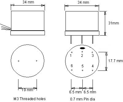
I made another transformer component with a 0.380" hole in the center -- also Pin7 of the Cinemag seems to be the ground pin on the input XLR, pin 6 would appear to be the shield for the preamp side, pin 2 is another transformer shield.
The sowter 3575 has a center-tap on the secondary -- not the case on the cinemag.
The sowter 3575 has a center-tap on the secondary -- not the case on the cinemag.
An externally hosted image should be here but it was not working when we last tested it.
jackinnj said:I made another transformer component with a 0.380" hole in the center
perfect. You have room to add the little M3/#4 holes as well for the side exit Sowter. The holes are in the same place on the Cinemag, but unfortunately the wires exit from the bottom of the can, so you cannot accommodate this version.

I moved the pins of the Sowter a few mills so as to avoid the "hole". The diameter of the new mounting M3 holes is 3.3mm.
I used a 50 mil via for the #18 stranded for the 0.47u/400V Auricaps
An externally hosted image should be here but it was not working when we last tested it.
SY:
pesky me again with beginner questions 🙂
Q: What is the function of R111 and R112?
(edit) A: voltage divider to float heaters up to some percentage of B+
If one was to try to use DC heaters, then are C106 and C107 still necessary? How do you float the heater in this case?
What is your PSU doesn't have a heater center tap, just a 0-6.3VAC winding, how should this be handled?
Finally, it seems that all the earth connections from the XLR, C106/C107, and the ground breaker should meet at the input transformer shield. Does this seem reasonable? Would there be any reason to add extra pads to the PCB here to make everything meet up here, as well as include spots for C108, D104, D105 on the PCB, linking analog ground to earth?
Thanks again!
With lack of a center tap, I suppose just use a pair of resistors to create one. With DC heaters, I'm not sure if you need to use the voltage divider or just connect one side to the main PSU ground... anyways, I'll wait for your answers 🙂
I'm in an airport at the moment, so I'll have to look when I get home. Offhand, I can't remember what C106 and 107 are. If they're the ceramic bypass caps, you still want them there irrespective of the supply- they'll filter out common mode garbage and RF that can couple to the cathodes.
R111,R112 are a voltage divider -- R111 drops about 340V so there should be 60V on the CT.
As the preamplifier warms up the neons glow -- until you start drawing some meaningful current.
As the preamplifier warms up the neons glow -- until you start drawing some meaningful current.
right, thanks guys.
So, if you don't have a CT, then make one, with say a pair of 270 ohm or so resistors and connect this "fake CT" to the voltage divider as in the schematic. In this case, the two ceramic caps would be before the "fake CT" and still connect to earth.
If you are using DC heaters, still use the two ceramic caps and connect the middle connection to earth (or maybe ground as Jack has it on his board). However, the question still arises, would you then connect the ground of the DC heaters to the voltage divider, or is this not necessary, and instead just tie it to either leg of the B+ supply?
- Home
- Amplifiers
- Pass Labs
- ImPasse Preamplifier