
Well, it's an unusually big imbalance. You usually see something like 82/100k to compensate for the gain imbalance when there's a resistor instead of a CCS in the tail.
Yes, the low resistance 1.5k common cathode resistor is the total Antithesis of a LTP (Long Tailed Pair), and is also the antithesis of using a CCS.
It will cause lots of 2nd order distortion; But More Importantly causes a reduction of the output stage's maximum power output.
Planned or un-planned, thats what that circuit gets.
It will cause lots of 2nd order distortion; But More Importantly causes a reduction of the output stage's maximum power output.
Planned or un-planned, thats what that circuit gets.
Thanks for the responses guys, I think it's planned, & output balance wasn't a consideration. I just wondered if such a big imbalance would cause problems.This thing drives a couple of EL34s to 40 watts.
It sounds great - if you're a guitar player. Mick Taylor plays one on the latest "That Pedal Show" Youtube video.
It sounds great - if you're a guitar player. Mick Taylor plays one on the latest "That Pedal Show" Youtube video.
PeteMcK,
Thanks for telling us up front in your Post # 1, that this is a Guitar amplifier!
Guitar amplifier designers Do plan ahead.
Hi Fi Stereo designers plan ahead Too.
But the goals are completely different; and so the circuits are completely different.
"All generalizations have exceptions"
Do you want to cause all the un-balanced signal to be only in the output stage?
Use a balanced CCS cathode coupled phase inverter.
Then Use a 6L6GC for 'Push', and an EL34 for 'Pull'.
Be sure to set the 6L6GC quiescent current = EL34 quiescent current (unless you want lots of lamination saturation that even starts at low power out).
This might be a new idea for most guitar amplifier designers.
Be creative, try it, and see what it sounds like.
Let us know.
Last edited:
Yes, many times by Yours Truly & Others.I’m pretty sure that’s been tried before.
Here is a Cunning Devil Mod by none other then Doug Hammond, you know, the transformer guy! 👍
And another from the distant past.😀
Attachments
jhstewart9, and others:
U Missed my point in Post # 6:
I said:
"Use a 6L6GC for Push, and an EL34 for Pull.
Be sure to set the 6L6GC quiescent current = EL34 quiescent current (unless you want lots of lamination saturation that even starts at low power out) . . . This might be a new idea for most guitar amplifier designers."
There is nothing in the above statement that talks about a self inverting amplifier.
It only talks about totally different output tube types for Push than is used for Pull.
Hints:
Use individual self bias resistors and individual bypass caps.
Then adjust the different bias resistors so that both tubes are at 50mA quiescent current (balanced quiescent current in each 1/2 primary).
The EL34 will have about 10,000 uMhos transconductance (10mA plate current change for 1V control grid change). Pentode mode.
The 6L6GC will have about 5,500 uMhos transconductance (5.5mA plate current change for 1V control grid change). Beam Power mode.
Given a +1V change to the EL34 control grid, and a -1V change to the 6L6GC control grid,
The un-balanced signal will be 4.5mA.
And so forth for higher changes of control grid voltages (always equal voltage change, but always out of phase).
Can you see the concept?
Thanks for reading!
Last edited:
I’m pretty sure that the mismatched types was a Tubelab experiment. He has brought it up before, don’t know if it was ever made practical.
You will end up with some saturation under drive. You may be better off overall with some mismatch in bias current, to give some headroom for the bias to shift in the other direction. One might try a bias servo, which would dial the EL34 side back (or 6L6 harder) as it’s driven harder. That would let you keep the 2fo and DC balance it out to keep the core out of saturation.
You will end up with some saturation under drive. You may be better off overall with some mismatch in bias current, to give some headroom for the bias to shift in the other direction. One might try a bias servo, which would dial the EL34 side back (or 6L6 harder) as it’s driven harder. That would let you keep the 2fo and DC balance it out to keep the core out of saturation.

Again, generalizations:
Guitar amplifiers are made to have some distortion.
Two different output tube types is one way to do that.
So is saturated laminations.
Yes, those are dynamically changing versus the signal level.
But trying to use unequal currents to undo the un-balanced transconductance of the different tubes, kind of spoils the idea.
It reduces the saturation and reduces the distortion. But if we do that, we are headed back to the Hi Fi and Stereo domain.
Pick a goal, they are not the same.
The whole idea for the Guitar amp was to distort, and saturate quite widely from low amplitude to high amplitude output.
Don't do the dissimilar output tubes, and then attempt to fix it.
Just take a knife, purposely cut yourself, and then put on antiseptic, and a bandaid?
I have seen Hi Fi Stereo amplifiers that use output tubes, one a Triode (push), and the other one a Pentode/Beam Power tube (pull).
I have Not seen a Hi Fi Stereo amplifier that used two different Pentode tube types, or two different Beam Power tube types.
Such as EL34/EL84; or 6L6GC/EL34
Can you show us some examples . . . Anybody, please?
Practical?
Depends:
If it is for Hi Fi Stereo, probably not.
If it is to achieve a particular and Unique "sound" on an electric guitar, it just may be practical.
Want to hear a good Bass Guitar sound, then listen to Marty Robbins original recording of "Don't Worry 'Bout Me"
Just my opinions.
Last edited:
Interesting ideas 6A3sUMMER, but I can't help thinking that for a guitar amp, if a self split PI will do all the tone heavy lifting, it would be more cost effective to use it to drive a pair of power FETs?
I have had my days using JFETs, MOSFETs, and BJTs.
Not what I am interested in anymore. So many things, so little time and energy.
And, I have yet to devote the time needed to build a vacuum tube guitar amplifier.
First, my friend and I need to finish building some electric guitars.
Wood, sandpaper, poly-coat, pilot holes, screws, pickups, bridges, tuners, potentiometers, switches, jack, strings, etc.
Guitar amplifiers . . . Perhaps someday.
jhstewart9,
Thanks!
That is very helpful.
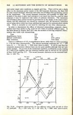
And 5% 2nd harmonic distortion was one of the [acceptable] standards for max power out.
(- 26dBc)
That article covered operation limited to Class A1 push pull.
It would be very interesting to see the results of operation in Class AB1 push pull.
I would expect the results to be far different.
Thanks!
That is very helpful.
And 5% 2nd harmonic distortion was one of the [acceptable] standards for max power out.
(- 26dBc)
That article covered operation limited to Class A1 push pull.
It would be very interesting to see the results of operation in Class AB1 push pull.
I would expect the results to be far different.
Zintolo, even though most respondants have gone off into the weeds, the particular amp is irrelevant. The thread is about the PI.
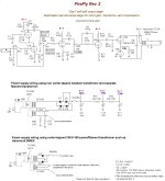
Should be in the guitar amp forum. Those folks will have some meaningful comments.It's guitar amp, presumably it's for distortion; point C is 330V
Which model guitar amp is it? Might be in Aspen Pittman's book including many schematics.
🙂
- Home
- Amplifiers
- Tubes / Valves
- Imbalanced PI