Very cool link!
Thanks,c2cthomas, ....
I have been trying to locate the only to samples that I had made in the late 90's and I still had them as of last year but now they have been miss placed. 🙁
jer
UR wlcome jer - with credit given to the OP of that link Neil Davis 😀😀
If you 10 year old "stack of stuff" is as deep as mine - well good luck finding anything for a couple of months!!! 😀😀
Gerald and Thomas, thanks for the info and updates, that patent in particular is a good read.
The tweeters are dismantled right now as they sounded good enough for at least a bedroom system. I replaced the tweeters in my B&W's for a week to try them out. So satin black for the steel and Eucalyptus burl for the bases.
Thomas I may have to throw a 2kg tweeter at you! or maybe one of my spare diaphrams I'm currently making up so you can trial them, they are an odd size though, most definitely not Great Heil sized.
Nick
Basicaly what I did was,
I first layed down some .25mil mylar and coated it with an extremely thin coat rubber cement.
Then I cut this in half so that I have two pieces of the same size.
On one peice I would carefully (of course) lay down some smoothed out 2" wide copper tape.
Then using some vinyl transfer tape (I had 24" wide rolls of it) I would lay out my pattern on it with some 1/8" or 1/16" pinstriping material so that the sticky side was out and then stick it to the cleaned copper tape.
Then carefully rub it down real good and peel off the transfer tape leaving the pinstriping pattern behind.
Then etch in ferric clhoride.
Rinse.
Lightly clean off any glue residue from the copper trace with some solvent (acetone).
Then take the other piece of rubber coated mylar and rub it onto the copper exposed side as it should be still tacky.
Sandwiching the voice coil in between the two pieces of mylar.
This seemed to add some rigidity to the diagphram as I was worried that the myalr was quite thin and might make a crinkely rattling sound.
But as you know making even folds proved to be very difficult.
So then I used the method to make a staight ribbon, I never tested either one.
Reason being was that, between working many 14 hour days in a week as a chef and the recording business was booming at the time and left me little time for projects and my need for quality sound was satisfied with the stuff we had in the studio as we had converted our house into the recording studio.
I did try to do this with a vinyl pattern cut on my vinyl cutter but the type of vinyl I had at the time was too sticky and I could not separate the vinyl from the copper tape with out destroying the thing.
I am sure this method will work with aluminium as well, just use sodium hydroxide (oven cleaner) as the etchant.
Jer
P.S. sorry about the font change as I don’t know which one I started with or how it got changed.
The straight ribbon I did had this shape with 4 or 5 stripes,
http://www.diyaudio.com/forums/planars-exotics/190642-pistonic-corrugation.html#post2601575
Ironicaly I never knew that a ribbon with that shape ever exsisted until I saw it posted the other day!
I had devolped this somtime in 1994 to 1996 as I don't remember the exact year.
I had alot going on back then with alot of different projects!
jer
Last edited:
There are two nice pics of AMT diaphragms on the ADAM site: X-ART | ADAM Audio GmbH The one showing the folded up diaphragm illustrates the width to depth ratio.
Ok, so I've not had the measurement system out so there are still no accurate specs on these things (YET, I will get there) but I went and bought some Cherry and after what feels like forever I've finished one tweeter.
And here she is:


The theme for these was always Steampunk.
Thanks for looking.
Nick.
And here she is:
The theme for these was always Steampunk.
Thanks for looking.
Nick.
Last edited:
Right so I tried some more measurements, I think I'll have to admit this is the best I'm going to get, it does however show how inefficient the tweeters are, which is a shame as they sound lovely.

Oh well I will have some leeway when designing the BSC.
Nick
Oh well I will have some leeway when designing the BSC.
Nick
Last edited:
Hi Nick ... I'm new here. (first post in fact)So I've made diaphrams, I have achieved an Re of around 3.2Ohms which shouldn't kill my amps and is close to the AMT-1 of 2.9Ohms.
I was having issues with torn foil so I started to tack it to the paper overlay with the required pattern on.
Used:
Sainsburys basics range kitchen foil.
5 micron Mylar (model airplane lightweight covering material)
2 micron Mylar (model airplane lightweight covering material)
3M Spray adhesive (for Photo mounting)
First I print a 1:1 scale drawing of my pattern on paper then I spray the back of this with a very light coat of glue.
I spray for as long as it takes me to make the sound "Tsch", just like the spray can!
This is then bonded to the foil, I do this as I was losing 90% of my attempts due to ripped foil, I'm now getting around an 80% success rate.
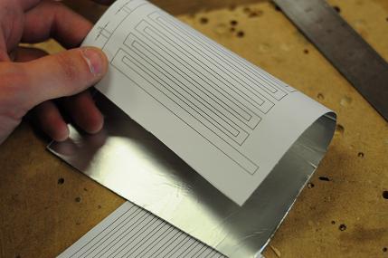
I then cut the pattern out of the paper/foil.
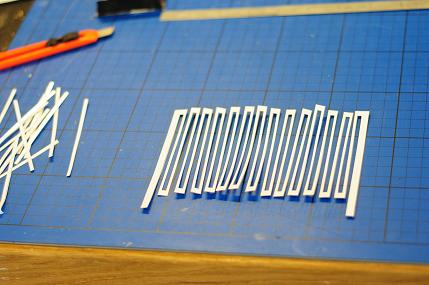
Next I turn the pattern over so the foil layer is uppermost and I spray the 5 micron mylar liberally with the spray adhesive.
(I mistakenly bought metallised 5 micron mylar so remove the metal with Mr Muscle foaming oven cleaner, it takes alu off a treat due to the NaOH!)
Once the glue is evenly on the mylar I stick it to the foil.
The next step is to remove the paper from the foil, this should be easy if you used little enough glue, if not I can recomment RS label remover and a cotton bud (Q-tip).
If you get the paper damp this should be enough to release the glue and prevent ripping, do not apply to the mylar!
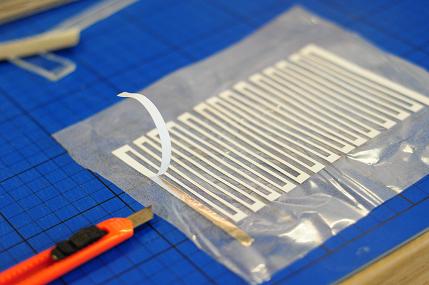
Once removed there should be sufficient tack on the 5 micron mylar left to stick down a layer of 2 micron mylar, this completes the diaphragm.
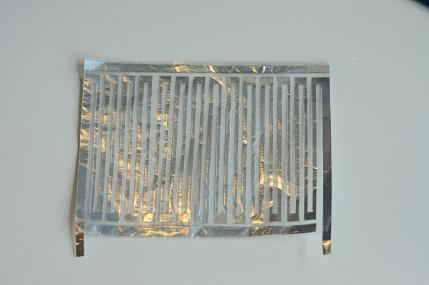
All that is left to do is fold the diaphragm. I use the edge of a plastic rule to get a nice rounded edge.
Nick.
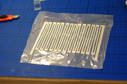
The diaphragms I've seen (have a pair of these from way back now) don't have the VC conductor laid out quite like you have in the above photo. The top band (thicker section) and the bottom band (thicker section) are joined to the side bands (thicker section) at all four corners.
Your top band would need to be lengthened to touch the side band(s) and the side bands would need to be lengthened to touch the bottom band. That is how the original diaphragm is laid out.
They also used a long strip on each side (out of the circuit) to fix the diaphragm to the frame via glue. Top and bottom was fixed to the frame with clear silicone.
Sort of appears like a die stamped pattern overlaid on one sheet of membrane as well. I mic'ed the sheet and it doesn't appear to be a lamination. I was reading the diy planar thread here and got to thinking about the authors use of the al tape (overlaid turns and all) ... and why this couldn't be used here as well. Turns out 3M has several types. Something along this order? Thickness seems close to original. Just needs slitting for width.
http://multimedia.3m.com/mws/mediaw...x_S4xmUev7qe17zHvTSevTSeSSSSSS--&fn=04320.pdf
What would it take to (geometry wise) to fabricate a LF diaphragm? Is it even possible?
There are many ways of creating the diaphragms and i designed a few, for me and the foil material i used, this layout gave me a usable resistance. Extending my strengthening strips would short my electrical path and make the serpentine pattern I have pointless.
I looked at short parallel serpentine patterns but resistances were far too low, there really are a thousand variations depending on the resistivity of the foil.
The the 3m tape might work but creating the turns could be awkward, and would create a thicker section of diaphragm.
I've considered trying to make a LF diaphragm, and there are examples on this site, I just dont have time right now, and I want to spend my disposable income elsewhere.
Nick
- Status
- Not open for further replies.
- Home
- Loudspeakers
- Planars & Exotics
- Image Request: AMT / Heil diaphragm.