Hi Nick
Well 3M makes some good stuff, so why not 😉
About keeping the diaphragm in place. I was thinking of using hot glue at the ends, gluing the diaphragm to the frame .... could that work?
Also you are using a strip of alu at the ends ... which is a good idea to keep the folds, but maybe it should be thicker ... was thinking about using some of that copper tape used for EMI screening and things ...
JVCC CFL-5CA Copper Foil Tape (Conductive Adhesive) at FindTape.com
Think it will be even easier to bend to right shape ... just a thought.
/Baldin 🙂
Hi Nick
Well 3M makes some good stuff, so why not 😉
About keeping the diaphragm in place. I was thinking of using hot glue at the ends, gluing the diaphragm to the frame .... could that work?
Also you are using a strip of alu at the ends ... which is a good idea to keep the folds, but maybe it should be thicker ... was thinking about using some of that copper tape used for EMI screening and things ...
JVCC CFL-5CA Copper Foil Tape (Conductive Adhesive) at FindTape.com
Think it will be even easier to bend to right shape ... just a thought.
/Baldin 🙂
Hot glue at the top and bottom could work but there could then be an issue with removing and replacing the diaphragm should you need to. I dont think that perfect spacing of the folds is necessary and as long as the folds are approximately in a plane everything seems to work, I do not intend to be fussy.
The alu folds at the top and bottom are folded over several times so they have a lot of strength, you could use copper but it would be much heavier and I dont really see the need.
Ideally one would use a wave shaped two piece plasic frame at the top and bottom to force the film into the correct position, this however would increase the requirement for accuracy in the cutting of the alu pattern.
Nick.
I vary much admire your work as I had attemped to build one of those several years ago.
I gave up because I never got the magnet structure built.
However I did come up with a method using coper foil and etching technique to make the Voice Coil on the mylar using materials for cutting and transfering vinyl decals and a vinyl cutter.
The other reason was that I had a hard time trying to fold up the diagphram so that it had even folds and pleats.
Keep up the great work. jer
The magnetic structure
Jer
Thanks for the comments, I would love to hear more about your etching technique, did you ever get reasonable resistance values from the voicecoils? mine were all trial and error!
Your post has reminded me to put up some of my steel chopping pictures, anyway first I ordered 6 lengths of 3000x13x3mm mild steel.
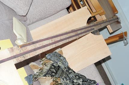
The next task was to bodge a jig together so I could cut the steel into more manageable lengths, my wife was NOT happy about our flat being used as a storage area so....
Several fag packet calculations later I had figured that trapeziums were needed, 45 degree cuts on one end and 90 degrees on the other which would make cutting easier as I would waste very little steel. The dimensions of the pieces parallel sides were to be 63mm/50mm and 50mm/37mm.
As I was in a rush to appease my wife, I decided to perform my cutting in two operations, first to cut ALL the steel to 100mm long rectangles, then later at my leisure to cut the trapeziums.
The pile of cut steel.
My boss at work is a happy chap and although I have a desk job, we maintain a lab for any small electrical and mechanical projects that pen pushers in other departments may require.
I had been explaining my plans and he just couldnt wrap his head around the tweeter working, I assured him it would so he gave his blessing to use the lab in my spare time to get things working. I will have to do some presentations once I've finished, all part of my personal development plan.
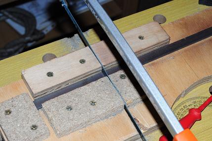
The next step was to make the diagonal cuts, this was achieved by putting the saw at 45 degrees through my cheap, bodged wooden jig.
This left me with approximately 320 pieces of rough cut steel, so out with the file.
My final task was to drill alignment holes through the steel pieces, all measurements were taken from the critical 45 degree cut ends and I used a pillar drill and my previous jig to drill the holes one at a time. I've misplaced the photos of that for the moment, but will post them when I find them (4 pcs and 3 camera in the flat!)
Thats all for now, and yes ALL the steel was cut by me, by hand.
Nick.
I vary much admire your work as I had attemped to build one of those several years ago.
I gave up because I never got the magnet structure built.
However I did come up with a method using coper foil and etching technique to make the Voice Coil on the mylar using materials for cutting and transfering vinyl decals and a vinyl cutter.
The other reason was that I had a hard time trying to fold up the diagphram so that it had even folds and pleats.
Keep up the great work. jer
Jer
Thanks for the comments, I would love to hear more about your etching technique, did you ever get reasonable resistance values from the voicecoils? mine were all trial and error!
Your post has reminded me to put up some of my steel chopping pictures, anyway first I ordered 6 lengths of 3000x13x3mm mild steel.
The next task was to bodge a jig together so I could cut the steel into more manageable lengths, my wife was NOT happy about our flat being used as a storage area so....
Several fag packet calculations later I had figured that trapeziums were needed, 45 degree cuts on one end and 90 degrees on the other which would make cutting easier as I would waste very little steel. The dimensions of the pieces parallel sides were to be 63mm/50mm and 50mm/37mm.
As I was in a rush to appease my wife, I decided to perform my cutting in two operations, first to cut ALL the steel to 100mm long rectangles, then later at my leisure to cut the trapeziums.
The pile of cut steel.
My boss at work is a happy chap and although I have a desk job, we maintain a lab for any small electrical and mechanical projects that pen pushers in other departments may require.
I had been explaining my plans and he just couldnt wrap his head around the tweeter working, I assured him it would so he gave his blessing to use the lab in my spare time to get things working. I will have to do some presentations once I've finished, all part of my personal development plan.
The next step was to make the diagonal cuts, this was achieved by putting the saw at 45 degrees through my cheap, bodged wooden jig.
This left me with approximately 320 pieces of rough cut steel, so out with the file.
My final task was to drill alignment holes through the steel pieces, all measurements were taken from the critical 45 degree cut ends and I used a pillar drill and my previous jig to drill the holes one at a time. I've misplaced the photos of that for the moment, but will post them when I find them (4 pcs and 3 camera in the flat!)
Thats all for now, and yes ALL the steel was cut by me, by hand.
Nick.
Last edited:
Not much of a chance to play this weekend with In-Laws and nieces to placate but I manged to get something that looks like a freq curve out of ARTA for the first time in 5 years. Please note this is just playing around and NOTHING in the system is calibrated especially the electret mic.
So without further introductions, I would like to present my (first) data:

Can anyone tell me how good the Panasonic electrets are above 10k?
Thanks
Nick.
So without further introductions, I would like to present my (first) data:
Can anyone tell me how good the Panasonic electrets are above 10k?
Thanks
Nick.
Last edited:
/24.JPG.pagespeed.ce.iFpMQIz4pR.jpg[/IMG]
Thats all for now, and yes ALL the steel was cut by me, by hand.
Nick.
After all of the cutting by hand and drilling your forearms must resemble Popeye's!!! 😀
To accomplish what you have inside of a small apartment (flat) is simply remarkable!!!! This should be a real inspiration to those that are limited for a work space. 😎
Attachments

I've dismantled everything at the moment to make some changes but with my first prototype which has a stupidly large 8.5mm wide air gap compared to the final 5.5mm I decided to do a comparison.
Anyway, I compared the tweeter to a Pioneer car speaker which alleges the following:
4Ohm, 90dB/W/m, 40Hz-35kHz.
These are the results, I think we can agree my measurement system needs some work!

Nick.
PS: Thomas, My arms and shoulders were aching for over a week, I did most of the cutting over 2 evenings so there was no hanging around.
Anyway, I compared the tweeter to a Pioneer car speaker which alleges the following:
4Ohm, 90dB/W/m, 40Hz-35kHz.
These are the results, I think we can agree my measurement system needs some work!
Nick.
PS: Thomas, My arms and shoulders were aching for over a week, I did most of the cutting over 2 evenings so there was no hanging around.
Last edited:
These are the results, I think we can agree my measurement system needs some work!
Nick.
The devil is in the details Nick. The number of folds the diaphragm - fold spacing - tension - depth - effective strength and uniformity of magnetic field.
There is a great number of things to consider and play around with. Take a very close look at the ESS diaphragm for hints. One of the 1st things I would suspect is the thickness of the diaphragm material and just how "stiff" (resistant to flexing) it is. ESS used different materials at times with mixed results as to how they performed.
Replacement diaphragms for the ESS speakers are available here in the States
(i.e. colonies) Parts-Express.com ? ESS Labs ? Air-Motion Transformer, Heil, Replacement Driver, Ribbon Tweeter, Replacement Diaphragms, AMT
and the purchase of one for testing your magnet structure with might be worthy of consideration. Obtaining one these ESS diaphragms would also allow you to give is a careful visual inspection and measurement which could be of value.
Keep up the good work!!!!
Thomas
My main point was to show how both responses drop like stones after 10kHz for both the conventional speaker and my DIY effort, this must mean I have issues with my measurement setup.
There was a post in another thread about pleat depth and upper frequency cut-off, from memory I'm currently running 4mm which should be good for around 20kHz.
I do intend to keep playing, I've read all the literature I can find from posts on this and other sites to the patents and promo material from manufacturers, all info is good if sifted properly for BS.
I won't be paying $90 for an ESS element as it does not fit with the "do it on the cheap" nature of this project, on which subject I still need to find plans or create a design for the lower frequency sections of the completed speaker.
Thanks for the continued comments and suggestions, nothing is discounted (except spending vast quantites of cash!)
Nick.
Thomas
My main point was to show how both responses drop like stones after 10kHz for both the conventional speaker and my DIY effort, this must mean I have issues with my measurement setup.
There was a post in another thread about pleat depth and upper frequency cut-off, from memory I'm currently running 4mm which should be good for around 20kHz.
Nick.
I had a friend that worked at the ESS plant in Sacramento and came up with a rig they used for folding the diaphragm. One of the problems they were facing was getting good consistency in folding and tension. The device resembled a couple of loooooong giant gears with the "teeth" spaced to intersect the diaphragm at the folding areas. That was needed for mass production tho - and you certainly do not need to make such a device for making just a few diaphragms - especially prototypes that you might be changing dimensions on. I do have an idea on how to do that folding if you need some help tho.
Your point on your test set-up is paramount. Without a proper testing rig and process you will be chasing your tail around and perhaps even go off on a wrong path. 😱
I know, I know, but hey I had to post SOMETHING, and at least I know its wrong, I'll keep working on the damn thing to try and get it up and running properly.
Nick.
Nick.
Hey Nick!!! Having worked on my fair share of prototypes I know where you are coming from. The work you have done to date is remarkable and something that very few would have taken to time or effort to do. Given your available resources and workspace I'm astonished that you have accomplished as much as you have and I congratulate you!!!
I hope i haven't offended you. My comments were supposed to be lighthearted. Maybe I should use more smiley faces.
work to recommence tomorrow.
Nick
work to recommence tomorrow.
Nick
Nick - I intended my remarks as positive and supportive!!!! As I stated - "I congratulate you"!!! Keep up the great work - and if I can be of any help please feel free to contact me!! 😀😀😀
Stupid bloody wood cutting /drilling AAAAAAAAAarrrrrrrrrrrrrrrrrrrrrrrrgggggggggggggghhhhhhhhhh
I cant drill any holes in the bits of wood I've got, that will result in a 6mm Gap, I'm getting so hacked off I could just bin the whole lot.
Nick.
I cant drill any holes in the bits of wood I've got, that will result in a 6mm Gap, I'm getting so hacked off I could just bin the whole lot.
Nick.
NCan anyone tell me how good the Panasonic electrets are above 10k?
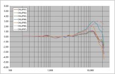
I few years back I purchased a ten pack of Panasonic capsules.
Attached is a plot of the calibration curves for 7 of them.
The other 3 were damaged by over zealous soldering 🙁
As you can see, all of them have a response peak in the top octave with roll off beyond that.
I was pleased to see two of them fit in a +/-1.0B window.
Calibration curves were measured by comparing response with a calibrated M51 microphone from LinearX.
M51 Microphone - General Purpose Low Distortion Measurement Microphone
One other thing to be aware of is that the output impedance of the capsules is rather high.
So, depending on the length and capacitance of the cable you use to connect the mic to your measurement system, you can easily get another -1db to -2dB roll off at 20kHz.
Attachments
According to Panasonic the mic's should be liniar to 20kHz. But I also see similar drop above 10-15k, as can also be seen on your measurements bolserst.
I'm using the Panasonic MCE-2000, which should be very similar to WM-61. Take a look at my mic here.
How close do you place the mic to the driver?
Try both very close (like 2-5 cm) and further away, like 30 cm and 1 m. Make syre that it is placed away from reflecting surfaces e.g. don't do the measurement on a table, which goes for both speaker and microphone.
Have you tried HOLMImpulse as a measurement tool? Think it is easier to get good results with than ARTA.
Anyway, don't get too much put off by your measurements over 10k .... what you have now in your first prototypes are brilliant. .... so don't give up. (also if you can get a good response to say 15k ... most of us over 20 can't hear much higher anyway 😉)
One thought:
The magnet structure you are using, is a "copy" of the old ESS AMT-1 kind of thing. I think that was used to make room for the enormous magnets used. With the availability of neos today, this is not necessary. Take a look at the newer designs from Mundof, Beyma and others. More efficient, and easier to build.
Question: Where did you find something about the pleat debth in relations to high freq response? .... would like to read that ...
Keep it up. Best regards Baldin 😉
Bolerst, thanks for the information, I shall harass some of my friends for a calibrated mike, I'm sure one or two may have one somewhere. My cables are DIY, thick solid core and short but I shall try some other cables.
Baldin, the information was in the following thread, its not exactly a published paper but my deeper diaphragms definitely had a lower roll off.
HERE
I am currently measuring from within the magnetic "horn" so that should minimise the effects, other structures are a possibility, but I dont know if they would be more efficient as I've not modelled them, however the newer shapes are definitely easier to use in a conventional speaker so that could be why they are made like that.
I chose the AMT-1 style for the steampunk appearance!
From what I have experienced the major factors in efficiency are, in no particular order, Material (magnetic structure and diaphragm), "completing" the magnetic circuit, magnet strength and air-gap size.
Nick
Last edited:
Hi Nick
I came across a couple of things that I found interesting and wondered if you might find them of some help.
Take a look at the link provide in #14
http://www.diyaudio.com/forums/plan...ne-ever-seen-anything-like-these-units-2.html
Also of interest patent 6111970 suspension for pleated ribbon transducer.
OTOH - ya might wanna throw something at me for starting you up a path of even more craziness!!!
Very cool link!
Thanks,c2cthomas, that was the article I had when I started to do my attempted!
Nick,sorry I have got back to you on my etching method It is very simple really.
I have been trying to locate the only to samples that I had made in the late 90's and I still had them as of last year but now they have been miss placed. 🙁
I will write up a detailed description for you shortly.
But the basic princepal is the same as making p.c. boards.
jer
- Status
- Not open for further replies.
- Home
- Loudspeakers
- Planars & Exotics
- Image Request: AMT / Heil diaphragm.