
Now that I have ATH and ABEC working properly, I'm able to come up with some fairly unorthodox waveguides. (My favorite kind.)
If you look at the response of this waveguide, it's not as smooth as can be. This is true.
But my goal here, is to fit the waveguide into an Ikea Kallax.
The obvious solution is a 13.5" x 13.5" square waveguide that fits into one of the Kallax "cubes"
This waveguide is very asymmetrical, and you would assume that it's asymmetry would lead to a wildly asymmetrical pattern But it doesn't have that; note that the vertical AND the horizontal beamwidth is close to 100 x 100 degrees.
Here's how this is working:
That last point is kinda hard to understand, I know. Took me a while to figure out myself.
Here's one way to visualize this:
Bottom line: Although this waveguide is wildly asymmetrical, it's pattern is fairly close to 100x100 degrees.
If you look at the response of this waveguide, it's not as smooth as can be. This is true.
But my goal here, is to fit the waveguide into an Ikea Kallax.
The obvious solution is a 13.5" x 13.5" square waveguide that fits into one of the Kallax "cubes"
This waveguide is very asymmetrical, and you would assume that it's asymmetry would lead to a wildly asymmetrical pattern But it doesn't have that; note that the vertical AND the horizontal beamwidth is close to 100 x 100 degrees.
Here's how this is working:
- The waveguide is only 314mm wide, and you would expect it to lose pattern control on the horizontal axis by 1083Hz. But the horizontal pattern is maintaining down to about 600Hz.
- The waveguide is 548mm tall and you would expect the pattern to lose control at 620Hz. But it's obviously going lower than that (I need to re-run the sims with a lower limit to determine how low.)
- What's happening is that the wavefront is wrapping around the Kallax. As the wavefront wraps around, it transitions from radiating into less than half space, but not quite full space. Because the output of the waveguide is radiating into a larger angle, that tends to reduce the output to the sides (EVEN THOUGHT THE WAVE IS BIGGER THAN THE WAVEGUIDE.)
That last point is kinda hard to understand, I know. Took me a while to figure out myself.
Here's one way to visualize this:
- If the waveguide is producing a 1khz wavefront, the wavefront measures 340mm x 340mm. The wavefront is completely controlled by the waveguide, which measures 548mm x 314mm.
- If the waveguide is producing a 500hz wavefront, the wavefront measures 680mm x 680mm. The wavefront is completely controlled by the waveguide, which measures 548mm x 314mm. On the vertical axis, the wavefront is almost completely controlled by the waveguide. On the horizontal axis, the edges of the wavefront are now wrapping around the front baffle. (Because the baffle is 416mm wide, and the wavefront is larger than that.)
- The important thing here, is that at 500Hz, the wavefront isn't radiating into half space OR full space, it's somewhere in between. If the wavefront was much MUCH larger than the baffle, the wavefront would be nearly omni. But it's not.
- I believe that when the wavefront is in that "grey area", it's radiating more to the front (which is half space) but less to the sides (because it's somewhere BETWEEN half-space and full-space.)
Bottom line: Although this waveguide is wildly asymmetrical, it's pattern is fairly close to 100x100 degrees.
Attachments

Forgot to mention:
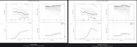
In the attached pics from post 22, there is a pic of what the enclosure looks like, a pic of the simulated vertical response, a pic of the simulated horizontal response normalized to zero degrees, and a pic of the simulated horizontal response normalized to 20 degrees off-axis.
With constant directivity waveguides, I like the Gedlee idea of listening off-axis, but to me, it looks like the diffraction slot in my design tends to favor listening with the speaker fired straight-ahead.
Bottom line: Although this waveguide is wildly asymmetrical, it's pattern is fairly close to 100x100 degrees.
Seems like that mostly, if not completely, due to its summed pipe end corrections.
I'll need to study that. I don't know how pipe end corrections affect directivity
Great minds think alike.
I've recently moved into a new house and have filled the space with kallax shelving. I was thinking to myself just last night that a small unity horn would be a great thing to have in one.
In my case I'm wondering if an offset horn (like the Danley genesis horn - sound is concentrated "off axis"), would be smart. In particular the front of my bedroom has a 2x4 kallax unit in each corner, and my bed is against the opposite wall in the centre, a horn firing directly ahead would tend to bounce the sound off the walls as opposed to concentrating it towards the centre of the room.
Additionally I have multiple 12" woofers lying around which fit quite nicely in the shelves. Simple sealed boxes would be fine for a bedroom I'd imagine.
While it's possible to manipulate pathlengths in a phase plug to 'throw' the sound in a different direction, I don't think I'd bother with that at home.
If you absolutely MUST use a device like that, I think the only good reason to would be if you absolutely can't physically rotate the speakers to send the high frequencies where you want them.
(As I see it, the Danley Paraline, Danley Layered Combiner and Heil V-DOSC are just elaborate phase plugs; they change the shape of the wavefront.)
The reason I (mostly) avoid them is because I've never been able to make one that performs as well as a conventional waveguide.
One other reason you might use one (which is important for prosound) is that if you use a vertical array of Paralines you can increase output at the back of the room by quite a bit AND you can increase the output overall because the sound is only expanding horizontally, not vertically. Check out my "Square Pegs" and "Sunshine" and "Stargate" threads on this forum for more.
I suppose I should have clarified that I wasn't intending to use a shaded amplitude lens or similar, just skewing the geometry of the horn to direct sound at a 45° angle or so. Funnily enough I recently came across Pelanj's kallax synergy project, which is almost exactly what I was imagining, the use of a ribbon/amt would provide greater vertical pattern control which I didn't even think of - quite handy in small acoustic spaces like a bedroom.
I'm not sure I'd be able to make an effective lense either, so I can quite readily understand your aversion to the concept. Fortunately the depth of the room is not great enough to make such a design particularly useful.
I'm not sure I'd be able to make an effective lense either, so I can quite readily understand your aversion to the concept. Fortunately the depth of the room is not great enough to make such a design particularly useful.
Don't let my friends at diyaudio find out, but I stuck one of those Yamaha "sound projectors" in my living room.
It's honestly kinda shocking how well they work.
They were $1700 new; I bought one on a whim from a Thrift Shop for $80.
I have my doubts that any of the new sound bars are this sophisticated; the original Yamaha Sound Projectors had full-on beam steering, and though it's a single sound bar, it 'throws' sound to the left and right wall.
So I'm not 100% ruling out these types of solutions, that put sound where it wouldn't "normally" go.
In my situation, I'm hosting friends and relatives for the holiday, and my stereo in the living room was cobbled together from a bunch of various amps and speakers and subs. I wanted a "tidy" solution that looked alright, so I tried the Yamaha, and was kinda shocked TBH.
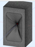
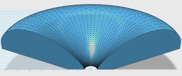
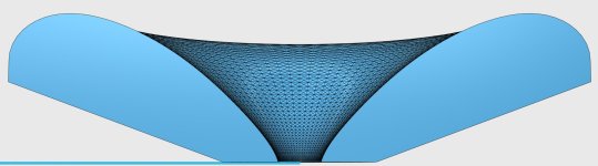
This is Mabat's "CE360" waveguide from his ATH thread. I wanted to see if it's possible to make a waveguide that's square instead of round, that performs comparably.
The reason I've posted a cutaway is because I needed to determine how deep the roundover is. It's 30mm deep. (When you use the "roundover" function with a square waveguide in ATH, the results aren't always perfectly flat. They are flat with a round waveguide.)
Here's the config file, which I cut and pasted from the ATH thread. There may be a couple of small changes.
; CE360
; 2021 Marcel Batik, licensed under CC BY-NC-SA 4.0
; Ath version 4.7.1[/b]
Throat.Angle = 12.24
Throat.Diameter = 26.4
Throat.Profile = 1
Coverage.Angle = 41.91
Length = 107.7
Rollback = 1
Rollback.Angle = 180
Rollback.Exp = 1.5
Rollback.StartAt = 0.585
OS.k = 1.30
Rot = 3.26
Term.n = 4.03
Term.q = 0.996
Term.s = 1.32
Source.Shape = 2
Mesh.AngularSegments = 64
Mesh.LengthSegments = 60
Mesh.RearShape = 1
Mesh.SubdomainSlices =
Mesh.WallThickness = 6
ABEC.MeshFrequency = 33000
ABEC.NumFrequencies = 100
ABEC.SimProfile = 0
ABEC.SimType = 2
ABEC.f1 = 500
ABEC.f2 = 20000
ABEC.Polars:SPL = {
MapAngleRange = 0,180,37
Distance = 2 ; [m]
}
Output.ABECProject = 1
Output.STL = 1
Report = {
PolarData = "SPL"
Title = "ATH Cutting Edge Series CE360"
Width = 1200
Height = 800
NormAngle = 10
}
Attachments

I'm beginning to see why Mabat is such a fan of waveguides that are NOT in a baffle.
I took the CE360, stuck it in a box, and the response shape changed quite a bit. The addition of the enclosure DID increase the directivity control to a lower frequency (something I've argued is possible for a few years now) but it changed the polar response and frequency response.
Perhaps the big surprise, was that there was quite a significant change on the vertical axis. IE, if the waveguide shape is similar to the box shape, things are good, once the dimensions of the box become asymmetrical (while the waveguide is symmetrical), things start to go sideways.
To me, this leads to three conclusions (which may be incorrect, TBF)
1) if your waveguide is symmetric, a box that is significantly asymmetrical may be a problem.
2) One could probably 'juggle' the box dimensions to improve this. Similar to using the "Golden Rule" for enclosure shape. Right now, the box I'm using has a height to with ratio of two to one, so that's about as bad as it gets.
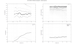
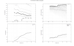
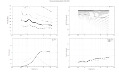
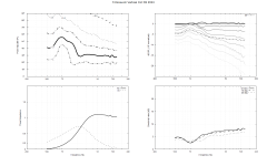
Attached are the vertical and horizontal sims, with the CE360 mounted in a box. Note that the issues with the response are caused by the box itself, not the waveguide. Also note that the response is simulated on-axis, not off-axis. (The previous ones were simmed at 20 degrees off axis.)
I took the CE360, stuck it in a box, and the response shape changed quite a bit. The addition of the enclosure DID increase the directivity control to a lower frequency (something I've argued is possible for a few years now) but it changed the polar response and frequency response.
Perhaps the big surprise, was that there was quite a significant change on the vertical axis. IE, if the waveguide shape is similar to the box shape, things are good, once the dimensions of the box become asymmetrical (while the waveguide is symmetrical), things start to go sideways.
To me, this leads to three conclusions (which may be incorrect, TBF)
1) if your waveguide is symmetric, a box that is significantly asymmetrical may be a problem.
2) One could probably 'juggle' the box dimensions to improve this. Similar to using the "Golden Rule" for enclosure shape. Right now, the box I'm using has a height to with ratio of two to one, so that's about as bad as it gets.
Attached are the vertical and horizontal sims, with the CE360 mounted in a box. Note that the issues with the response are caused by the box itself, not the waveguide. Also note that the response is simulated on-axis, not off-axis. (The previous ones were simmed at 20 degrees off axis.)
Attachments

- Home
- Loudspeakers
- Multi-Way
- Ikea Unity Horn