Moreover, having the capabilities of DSP, you need to go in the direction of active amplification, i.e. put an amplifier for each speaker, and give the crossover function to DSP. Active speakers are very flexible in setup and do not require much time to reconfigure the crossover.
I'm much better computers than speakers so I'm good with that. I do prefer if the speakers sounds good before DSP, and although I wouldn't mind using active crossover in the design phase, I eventually want to be able to design passive XO's as well.
If the hiss is produced by the tweeter power amp, you might use an Lpad to reduce it, and increase the signal gain to compensate.
If the hiss is produced by the tweeter power amp, you might use an Lpad to reduce it, and increase the signal gain to compensate.
In which case it would be possible to EQ it away as well, right? But again, I'd rather the speaker/box sounded good before I start EQ:ing.
Last edited:
I'm still a bit annoyed. Although OB seems to be the dominant design for these elements, people seems to place them in anything from TL's to vented boxes without problems. And here I go with a fairly spacious box and simple design, but no.
I get grumpy when I don't understand what is causing the problem 🙂
I'm traveling at the moment so I can't experiment for a week or so, but when I'm back I will switch out the elements to check that both sounds the same. And also check if I experience the hissing noise if I run an element in an OB.
I get grumpy when I don't understand what is causing the problem 🙂
I'm traveling at the moment so I can't experiment for a week or so, but when I'm back I will switch out the elements to check that both sounds the same. And also check if I experience the hissing noise if I run an element in an OB.
Last edited:

Nonlinear distortions of the speaker associated with the value of the output resistance of the signal source are usually in the upper range of the speaker's operating frequency. Which in some cases allows you to simply reduce the frequency range of such a speaker and forget about this type of distortion. Below is a picture of nonlinear distortions of a similar mid-range speaker with a direct connection to a voltage amplifier (red graph) and with different values of reactive resistance between the speaker and the amplifier. Based on its distortions and frequency response, the frequency range of its operation was chosen from 300 Hz to 2.5 kHz. This saved me from the need to use additional reactive resistance between the voltage source and the speaker.

A speaker that works well in a narrow frequency range is much easier to make and they are more readily available and cheaper than speakers that cover a larger frequency range. Therefore, it is much easier to find a good speaker at an affordable price for speakers that provide three frequency bands.I do prefer if the speakers sounds good before DSP,
Passive crossovers are limited in their capabilities. And sometimes these limitations are insurmountable. Of course, this is strictly your business, and you decide what suits you best. But personally, after mastering the capabilities of DSP, I am not going to return to passive band division, it is difficult, cumbersome, time-consuming, and a passive crossover does not allow you to achieve some of the results that DSP allows you to achieve.and although I wouldn't mind using active crossover in the design phase, I eventually want to be able to design passive XO's as well.
No, you can't EQ hiss from the power amp. You can put components between the amp and speaker.
If you try to EQ you will only reduce the treble at the same time.
Check. The power amp in this case is a Fosi Audio ZA3 fed by a iFi Zen Dac v2.
Below is a picture of nonlinear distortions of a similar mid-range speaker with a direct connection to a voltage amplifier (red graph) and with different values of reactive resistance between the speaker and the amplifier. Based on its distortions and frequency response, the frequency range of its operation was chosen from 300 Hz to 2.5 kHz. This saved me from the need to use additional reactive resistance between the voltage source and the speaker.
For my understanding, the "reactive resistance between the speaker and the amplifier" in this example was passive XO components in the existing network?
If that's the case, if I, for example, used an XO (L-pad or similar) to bring down the 10db rising treble in the speaker (instead of DSP), it could impact the THD as well? (I'm thinkling that since I want to learn XO anyway, it might be an interesting experiment for me to start getting my hands dirty).
In the example shown earlier, only air inductance of different ratings was connected in series with the speaker.For my understanding, the "reactive resistance between the speaker and the amplifier" in this example was passive XO components in the existing network?
The speaker has different sources of nonlinear distortions, and the source that is discussed in my post can be compensated a little from the side of the signal source, and for example, nonlinear distortions associated with the principle of operation of the diffuser cannot be compensated from the side of the signal source.
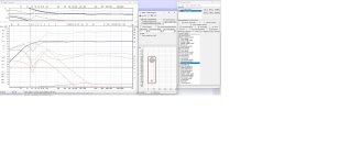
I quickly modelled the driver, Tang Band w8-1808 in Basta in a 54L vented box with QL=10. Vented because Basta does not do Voigt pipes, but nevertheless is a good approximation.
F6 is at roughly 36Hz, not a bad result.
To take care of the rising response and also baffle step I inserted an LCR network between the driver and the source.
As I said a quick simulation.
The values are:
L 1.2 mH
C 2 uF
R 5 ohm
This results in a quite flat response with 90 dB overall SPL, so dynamics are more or less preserved.
Below is a screenshot of the whole thing.
It shows amplitude, phase, impedance, max output level (MOL), cone excursion, cone excursion at MOL, baffle step.
@Fungrim, as you are from Sweden, get a copy of Basta, which is the brainchild of another swede, Svante:
http://www.tolvan.com/index.php?page=/basta/basta.php
It is not the perfect simulation tool but it is very powerful and very easy to use. And in combination with Hornresp, and possibly other pieces of SW you'll get the result you are after.
Have fun.
Attachments
Last edited:
- Home
- Loudspeakers
- Full Range
- Ideas around a rising frequency response in a TQWP