My experiments with a center tapped transformer lead to some fireworks, so perhaps two separate secondaries and the counter intuitive phasing is indeed a must.
Min Input = 6Vac
Max Input = 40Vac
Continuous load = 5A
Peak load = 8A
Regards,
Tibi
Hi Tibi,
Will this be available here or via distributors?
Perhaps even lower voltage versions for tube heaters?
Regards, Gábor
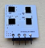
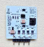
Just finished to mount first Saligny HV. These mosfets are very like unobtainium. Low Rdson and high Vds is tough combination.
Some hard tests will follow to see what this 30mm x 30mm baby is able to deliver.
Regards,
Tibi
Some hard tests will follow to see what this 30mm x 30mm baby is able to deliver.
Regards,
Tibi
Attachments
Last edited by a moderator:
Watching with interest, a couple of those would be perfect for a new amp project I'm planning if they perform like the first saligny.
Hi Tibi,
Glad to see the prototype there, I'm interested in this for preamp circuits as well. Hopefully the price makes +/- PSUs feasible to get above 300V total for output stages too. It'd be a shame to have all that current capability unused 🙂
Glad to see the prototype there, I'm interested in this for preamp circuits as well. Hopefully the price makes +/- PSUs feasible to get above 300V total for output stages too. It'd be a shame to have all that current capability unused 🙂
I can confirm that LT4320 will work just fine in such configuration, CT transformer, because I already used in several applications.
What matter is phase on secondaries to be same.
Some symmetric transformer secondaries are winded at once and this lead to one center taped secondary, but with two sections in anti-phase. This do not matter much when is used with two diodes for rectification.
So, my advice is to use a transformer with two separate secondaries and make sure these are in phase, or use two transformers each with one secondary and, again, make sure these are in phase.
Regards,
Tibi
Tibi,
I have a transformer with a single secondary: +42 & -42 referenced to a single CT. Is it possible to use 2 x LT4320 and feed one of them CT and +42VAC, and the other -42VAC and CT, and thus feed 1 rail from the output of one 4320, and the other rail from the output of the other, with CT as defining ground between the rails? In this case the phase difference wouldn't matter, no?
Does the 4320 see the input as floating, and thus it defines "0 crossing" as midpoint of sin wave?
Forgive me if this is a stupid question, I'm reading this thread and the other "4320 based rectifier thread", but am still not clear if I can use the 4320(s) with my transformer.
Just finished to mount first Saligny HV. These mosfets are very like unobtainium. Low Rdson and high Vds is tough combination.
Some hard tests will follow to see what this 30mm x 30mm baby is able to deliver.
Regards,
Tibi
How's this development working out Tibi?
I have a project in-hand where I think I could make good use of a pair of these; 105VAC transformer secondary.
Last edited:
Tibi,
I have a transformer with a single secondary: +42 & -42 referenced to a single CT. Is it possible to use 2 x LT4320 and feed one of them CT and +42VAC, and the other -42VAC and CT, and thus feed 1 rail from the output of one 4320, and the other rail from the output of the other, with CT as defining ground between the rails? In this case the phase difference wouldn't matter, no?
Does the 4320 see the input as floating, and thus it defines "0 crossing" as midpoint of sin wave?
Forgive me if this is a stupid question, I'm reading this thread and the other "4320 based rectifier thread", but am still not clear if I can use the 4320(s) with my transformer.
You attached the answer (from tvicol) in your post. Please read carefully.
You attached the answer (from tvicol) in your post. Please read carefully.
Would you be referring to,
"This do not matter much when is used with two diodes for rectification."
I first understood that he was referring to traditional rectification. Are you saying it refers to use with the 4321? Or am I entirely missing your point?
If I'm not missing your point then it's good news and I will proceed.
Ron
It says that you can use 2 ideal rectifiers in your situation BUT that both windings need to be connected right. They usually are connected right with CT transformers but if you have the accidental other type you will have smoke.
So: you need to verify that your transformer has both windings connected right. That is all. And please mention transformer with its AC voltages. You mentioned a transformer with + and - 42V which is wrong terminology. Using the right terminology works best for all.
Do not connect anything to the secondary side. Plug in the transformer (work safe!) and now measure between the outer connections and ignore CT. If you see the specified voltage x2 you can continue. If you see a very low voltage they are connected wrong for the LT4320 solution.
Originally Posted by tvicol
I can confirm that LT4320 will work just fine in such configuration, CT transformer, because I already used in several applications.
What matter is phase on secondaries to be same.
Some symmetric transformer secondaries are winded at once and this lead to one center taped secondary, but with two sections in anti-phase. This do not matter much when is used with two diodes for rectification.
So, my advice is to use a transformer with two separate secondaries and make sure these are in phase, or use two transformers each with one secondary and, again, make sure these are in phase.
Regards,
Tibi
So: you need to verify that your transformer has both windings connected right. That is all. And please mention transformer with its AC voltages. You mentioned a transformer with + and - 42V which is wrong terminology. Using the right terminology works best for all.
Do not connect anything to the secondary side. Plug in the transformer (work safe!) and now measure between the outer connections and ignore CT. If you see the specified voltage x2 you can continue. If you see a very low voltage they are connected wrong for the LT4320 solution.
Last edited:
Do not connect anything to the secondary side. Plug in the transformer (work safe!) and now measure between the outer connections and ignore CT. If you see the specified voltage x2 you can continue. If you see a very low voltage they are connected wrong for the LT4320 solution.
OK. I have a 120 VAC in / 84 VAC out transformer with CT. Secondaries are definitely in phase. I can use this transformer with 2 x 4320 to feed +/- 60 VDC rails on my amp. If this is true I can go ahead and push the button on my Digi-key order.
Thanks for the help getting clear on this!
(If I'm not clear on this, let me know.)
Ron
Hard one still as the LT4320 has a absolute maximum input of 80V AC. Well I don't know, I haven't used them like that so I can not give hard evidence. In fact I just finished my first PCB's but boy they measure very well! I would take the challenge as I see the logic behind it when reading tvicol's post but things can be damaged if it does not work out OK.
I think you need to PM tvicol as het has quite some experience. Or the member that had them ending up in smoke (some posts ago). I would be very sorry if I misinterpreted and gave you non optimal information.
I think you need to PM tvicol as het has quite some experience. Or the member that had them ending up in smoke (some posts ago). I would be very sorry if I misinterpreted and gave you non optimal information.
Last edited:
Just to clarify, I was proposing to connect 1 lead of the secondary and CT to one 4320 so that it would see only 42VAC, or ~ 60 VDC at the output. I would connect CT and the other lead of the secondary (the out-of-phase counterpart) to the other 4320. I would then measure potential between outputs of 4320 in order to find the pair which are (hopefully) at zero potential--these would define 0 volts between my rails, with the remaining outputs at +/- 60 VDC.Hard one still as the LT4320 has a absolute maximum input of 80V AC.
I guess the best way is to try it out (carefully) and see what happens. I may also buy a smaller transformer, 12 VDC or so, and see if the idea works at those low voltages before trying it on my larger transformer.
Ron
Tibi,
I have a transformer with a single secondary: +42 & -42 referenced to a single CT. Is it possible to use 2 x LT4320 and feed one of them CT and +42VAC, and the other -42VAC and CT, and thus feed 1 rail from the output of one 4320, and the other rail from the output of the other, with CT as defining ground between the rails?...
No, it's not possible. Is not possible with two normal diode bridges either.
You need two separate secondaries each with his own bridge.
Regards,
Tibi
How's this development working out Tibi?
I have a project in-hand where I think I could make good use of a pair of these; 105VAC transformer secondary.
Development has ended. Production is hard. Sourcing the mosfets delayed production in mid November.
Saligny HV is performing above my expectations. It was tested in 4 amplifiers. Two Class A, one AB and one D. Sonic improvement was substantial in all of them.
So far any circuit that got synchronous rectification got far better performance.
Regards,
Tibi
Thanks Tibi. So can I look forward to being able to make a purchase soon?
If so, I think that with their current capacity (25A?) I could run my two CLCLC power supplies off one Saligny HV? I guess they'll be quite expensive and not readily available so that arrangement might suit my pocket and avoid me being too selfish by buying more than I actually need.
What will be the means of purchasing them - through your website?
Cheers
Last edited:
If you see the specified voltage x2 you can continue. If you see a very low voltage they are connected wrong for the LT4320 solution.
It is exactly the opposite. You can have a centre tap working with a single 4320 only if you construct the centre tap yourself out of two separate secondaries. No factory made centre tapped transformer will work.
This should be mentioned at the first post of this thread.
Thank you very much for your input. So just to confirm, I can implement 4320 in my +/- 60 VDC amplifier, but I need a different transformer with two sets of secondaries which are in phase, + two 4320's?No, it's not possible. Is not possible with two normal diode bridges either.
You need two separate secondaries each with his own bridge.
Regards,
Tibi
Thanks again,
Ron
- Home
- Group Buys
- Ideal bridge rectifier GB