(Apologies in advance if it's in the wrong place.)
Would a kit be a good idea? Or just dive in? For context, I'm part-way through a S.E. MOSFET design at the moment, with a long-tailed pair of transistors, and I'm specifically making it a current amplifier (although the output impedance may be reduced with a parallel resistance, for example).
But I'm already thinking about a follow-up project -- maybe getting something like a Korg Nutube to be one of the stages. We covered MOSFETs at school, but I can't remember valves ever being mentioned. Although I'd been forewarned that valves had low gain and high noise. However, there was something that I remembered about microphones -- if you double the surface area, you get 2× the signal amplitude. but only 1.414 times the noise, for a net gain of 3dB. I'm guessing the same principle could used in designing a valve amp, especially if the tubes are miniature. But I don't know for sure. And I'd like to understand the gain and other performance curves, and why they are the shape that they are.
It might take at least 10 threads in order to cover your observations and questions.
I always find that a good place to start is the ARRL Radio Amateurs Handbook, especially the versions from the 1950s and 1960s.
But do not loose heart, you will get some good answers and good suggested reference books to learn from on this forum, just by starting this thread.
Yes, some kits are great learning "lab" exercises too.
Please remember that what you learned in school sometimes works according to the following rule:
"All Generalizations have exceptions".
Last edited:
Definitely read the safety "sticky". The voltages found in tube circuitry can be deadly dangerous.
That you have an understanding of FETs will help you understand tubes, as both are voltage controlled and high impedance in nature. Tubes are high voltage, low current, depletion mode devices. FWIW, the current/voltage curves of FETs and pentode vacuum tubes are quite similar in appearance.
Your command of English appears to be excellent. So, try to acquire a copy of the 1st or 2nd edition of "Basic Electronics for Scientists" by James Brophy. Free material available off the WWW is NEETS, which is U.S. Navy training material.
Look for a used tube amp and refurbish it. This is much cheaper than even a kit, and will give you valuable experience.
Pete Millets starving student is a perfect first build, IMHO. Also there’s a nice cover article on WTFAmps.com
When picking a specific project I think the first requirement to consider is output power. That will inform on topology. From there you can think about cost. Once you see the cost you may start to think about risk - meaning a risk averse approach like using a known kit would be better than trying to get it all worked out yourself.
Do you know what speakers you be using, how sensitive they are, and how loud you like to listen?
Do you know what speakers you be using, how sensitive they are, and how loud you like to listen?
A sister thread here is entitled "Gold mine of DI¥ audio tubes schematics from Japan".
Have a look at these and pick something that it would be possible to source the parts for.
While you wont get their subjective impressions out of an amplifier's article (for obvious reasons) you will get a schematic / parts list.
At least it'll be an amazing journey through what people have built who are audiophiles in Japan. Hopefully inspirational, to boot!
If you want to learn about valves I'd recommend building a little 3-5w two valve amplifier and design it yourself, all the info needed is here - How to design valve guitar amplifiers Merlins site is brilliant giving practical hands on info. All you'd need after you have a mains tfmr is a few caps, resistors and two valves an ECC82/3 and a EL84, that and a cheap SE output transformer. Oh, and two valve bases. Getting an old amp out of a record player as rayma suggested in post #4 is a good idea, then strip it and re-design by drawing load lines etc.
I learned more in 10 minutes mucking about on the bench than from hours of reading. Put the two together (practical & reading) and you should soon pick it up.
Andy.
I learned more in 10 minutes mucking about on the bench than from hours of reading. Put the two together (practical & reading) and you should soon pick it up.
Andy.
If you want to learn about valves I'd recommend building a little 3-5w two valve amplifier and design it yourself, all the info needed is here - How to design valve guitar amplifiers Merlins site is brilliant giving practical hands on info. All you'd need after you have a mains tfmr is a few caps, resistors and two valves an ECC82/3 and a EL84, that and a cheap SE output transformer. Oh, and two valve bases. Getting an old amp out of a record player as rayma suggested in post #4 is a good idea, then strip it and re-design by drawing load lines etc.
I learned more in 10 minutes mucking about on the bench than from hours of reading. Put the two together (practical & reading) and you should soon pick it up.
Good afternoon fro Greece! You can build an RH84 amplifier! It is perfect for the first build! Very easy to construct and super fine sound from this circuit! Search here,and you can find schematics,and opinions,or search in google! You can not disappointed, from this circuit!
Andy.
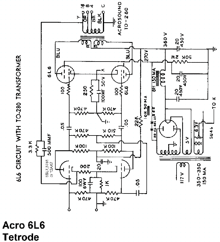
I started with a push-pull 6L6GC amplifier- you can start with an SE design or an EL84 push-pull, but make sure you choose something that will actually be useful to you. If you have inefficient speakers and a large room, don't even think about building a SE amplifier.
Morgan Jones's book on valve amplifiers is a good one and one I should have gotten before I started.
Do plenty of research, choose a good, solid design, and plan every aspect before you start building it.
Morgan Jones's book on valve amplifiers is a good one and one I should have gotten before I started.
Do plenty of research, choose a good, solid design, and plan every aspect before you start building it.
I built this as my first amp... Worked so well I didn't know it was working until I played a signal (I was used to tube amps humming when they were warmed up). I used separate cathode resistors (500R) for improved balance.
If you your amplifier must drive speakers, my suggestion to get a good output transformer(s) and build from that. A Toroidy TTG-EL34PP, as example (UL push-pull 6.6k 50W 200mA 590H). It will cost some money but there are several benefits:
a) you will get real Hi-Fi quality. It will drive circles around any transformer supplied with cheap tube kits, and some commercial amplifiers too.
b) you will avoid several build issues that arise from bad transformers (such as instabilities and bandwith limitations).
c) you will have more options, such as the ability to drive most modern speakers and use several different tubes.
d) if ultimately tubes will not please you, it is easy to sell it at minimal loss.
One other recommendation- use one of the "standard" output tubes like 6L6, EL34, 6BQ5, etc. There are lots of schematics for these, tubes are easy to get, and their behavior is known and predictable. You can build around new production tubes that have been matched and burned in- this greatly reduces the chances of tube failures causing issues. Contrary to what some people say, most new production tubes are of excellent quality.
Everything you ever wanted to know is in the Radiotron Designer's Handbook by J Langford-Smith. For audio specific gear you may want to read the book Valve Amplifiers Third Edition by Morgan Jones. To construct stuff read Building Valve Amplifiers by Morgan Jones.
If it was me, I would get a PCB for a proven design and then collect the parts and build it. If you buy old gear and a transformer is broken you may discover that a replacement is not available and a substitute does not fit.
Don't be surprised that with old gear you may end up spending as much as when you made something from scratch.
Last edited:
If you your amplifier must drive speakers, my suggestion to get a good output transformer(s) and build from that. A Toroidy TTG-EL34PP, as example (UL push-pull 6.6k 50W 200mA 590H).
I like that suggestion. Like the winder, the OP is in Poland and would get good stuff, without brutal shipping costs. That "iron" would work in something built along Harman/Kardon Citation V lines. The Cit. 5 is a superior implementation of Mullard style circuitry and Mullard style is "idiot resistant". 5881 equivalent Russian 6Π3C-E (6p3s-e) O/P tubes would yield at least 40 WPC and are modest in cost.
Possible "incremental" improvements to the Cit. 5 include constant current sink (CCS) loading of the phase splitter's tail and regulated O/P tube screen grid (g2) B+. The idea of ultra-linear (UL) mode, instead of full pentode mode "finals" could be entertained.
Attachments
If it was me, I would get a PCB for a proven design and then collect the parts and build it. If you buy old gear and a transformer is broken you may discover that a replacement is not available and a substitute does not fit.
Don't be surprised that with old gear you may end up spending as much as when you made something from scratch.
I'm probably in the minority who will suggest against buying a PCB as a beginner. The reason for this is that if you build the amp point-to-point (or if you're really nuts, design your own PCB), you will be forced to learn about layout, grounding schemes, noise, etc. It is more than doable for a beginner to build an amp point-to-point.
I recognize that this may lead to more failed projects, frustration, etc. I don't consider using a PCB to be "cheating" or anything like that, however I do think that building point-to-point will be the best learning experience.
Maybe I'm not getting the point of DIY, but for me it's all about what I can learn. My first tube amp didn't work quite right when I first built it. It passed audio, sure, but it had way too much gain and was rather noisy. I ended up shelving it for a while, then re-doing the grounding scheme. If I had bought a proven PCB, I wouldn't have gotten the experience of troubleshooting it.
Also, get a steel chassis. Yes it's harder to work, but for a big amp you may have 40 pounds worth of transformers on it. The first amp I build used what equates to an aluminum hammond chassis. It's pretty squishy, especially under the power transformer. It's structurally sound, sure, but in hindsight the chassis I used wasn't a great choice.
If you need a strong chassis, use a Thick aluminum top, and wood all around the sides.
For years I have fought a steel chassis, it magnetically transmits hum from the power transformer and from the B+ choke all the way across the chassis to the output transformers.
Hum, Hum, Hum.
My aluminum chassis work fine.
For years I have fought a steel chassis, it magnetically transmits hum from the power transformer and from the B+ choke all the way across the chassis to the output transformers.
Hum, Hum, Hum.
My aluminum chassis work fine.
If you need a strong chassis, use a Thick aluminum top, and wood all around the sides.
For years I have fought a steel chassis, it magnetically transmits hum from the power transformer and from the B+ choke all the way across the chassis to the output transformers.
Hum, Hum, Hum.
My aluminum chassis work fine.
I've never had that problem, but I could definitely see how it could be. I always isolate the transformers (with a ground connection, of course), so that may have something to do with it.
Thick aluminum is great if you can source a suitable chassis, though it can be a pain to finish. The main point I was making, however, is that the generic Hammond aluminum chassis are quite thin.
The hum is magnetically coupled by steel, not electro-statically coupled by steel.
Electro-static coupling has a completely different cause.
I aim for less than 100uV hum on both SE and PP amps. And I get that without the benefit of Global Negative Feedback (GNF, which reduces the hum of all stages except the first stage).
Electro-static coupling has a completely different cause.
I aim for less than 100uV hum on both SE and PP amps. And I get that without the benefit of Global Negative Feedback (GNF, which reduces the hum of all stages except the first stage).
The hum is magnetically coupled by steel, not electro-statically coupled by steel.
Electro-static coupling has a completely different cause.
I aim for less than 100uV hum on both SE and PP amps. And I get that without the benefit of Global Negative Feedback (GNF, which reduces the hum of all stages except the first stage).
I usually don't bother going quite that low, so I may not have noticed the issue before. My goal is about -80dBu after feedback if possible, though I have settled for less before. How much of the residual noise is caused by magnetic coupling through a steel chassis I cannot say. I haven't noticed more of an issue when using steel chassis versus aluminum, but that's not to say it isn't contributing.
- Home
- Amplifiers
- Tubes / Valves
- I'd like to make my first tube amp. Where do I start?