I was fortunate to be gifted a pair of globe 50s last christmas.
Now I want to make a simple 50 amp using these tubes, and am aware of the 10K grid resistor issue.
What if I use a 417A with plate choke, cap coupled to the 50 with grid choke?
Will the 417A have enough grunt to drive the 50?
If this will work, how do you compute for the driver parameters when using a plate choke?
I'm no designer so pardon my ignorance. But I can use TubeCAD")
Now I want to make a simple 50 amp using these tubes, and am aware of the 10K grid resistor issue.
What if I use a 417A with plate choke, cap coupled to the 50 with grid choke?
Will the 417A have enough grunt to drive the 50?
If this will work, how do you compute for the driver parameters when using a plate choke?
I'm no designer so pardon my ignorance. But I can use TubeCAD
Konnichiwa,
Sounds fine. I used very much the same scheme when driving a 300B operated rather a lot like a 50 (350V/60mA), main difference was I used a 437A as Driver, at 170V/12mA, not a 417A.
Yes, you will have to operate the valve quite hard, but it will. Use around 2.5V Bias, 170V Anode or around 220R Cathode resistor and 170V on the Anode. Adjust the +B dropper/decoupling resistor to get the anode voltage right. Under those conditions the 417A should be able to swing around 200V Peak-Peak, enough to drive 300B or 50 well past clipping.
Same way as for resistor load really, except the Choke approximates a near infinite Anode load but with a low DCR.
If you have a 50 operated at 400V/55mA with -70V Bias (read 1K2 Cathode Resistor) and a 3K5 load you should get 3.5 to 4 watt at clipping and you need a +B of 470V plus Output Transformer losses.
If you take this +B you should use a slow warmup rectifier if you derive the Anode supply for the 417A from that HT line without regulation. If you do, use a pair of "dropper" resistors, giving you RCRC decoupling for the driver stage. This tends to sound better than just RC decoupling.
The kind of anode load chokes I used had around 1K DCR and thus would drop around 12V DC in operation. So, in self bias mode for the 417A we would have a supply to the top of the anode choke of 2.5V (Bias) + 170V (A-K Voltage) +12V or 184.5V. For ease of calculation we use 185V.
If our +B is 475V under normal load we need to drop 290V at 12mA DC current. This suggests 24K for the total resistor in the supply line, using a pair of 12K resistors and 10uF MKP Capacitors should give a nicely filtered 185V for the 417A.
Other options are to derive the Driver +B via Zenner Diodes, Gas Stabilisers, an OB3 and OC2 in series will give around 195V regulated for the 417A driver stage. Or you could use fancy shunt regulators, solid state or hybrid.
You could even build a seperate supply of 185V for the Driver Stage, say rectified with EZ80 and LCLC Filtered. It all depends how far you want to go.
To me a pair of Monoblocks using seperate supplies might be interesting. Of course, if you have seperate supplies you might as well go for direct coupling between driver and power stage and in effect roll the gridhoke and anode load choke into one.
Another note, if you make the heater Supply switchable you could also use 300B's and if you have an Output Transformer with enough primary inductance to allow mistmatching to twice it's nominal 3K5 primary impedance you could select between 300B, 50, VT-52 and VT-25/10Y...
Sayonara
arnoldc said:Now I want to make a simple 50 amp using these tubes, and am aware of the 10K grid resistor issue.
What if I use a 417A with plate choke, cap coupled to the 50 with grid choke?
Sounds fine. I used very much the same scheme when driving a 300B operated rather a lot like a 50 (350V/60mA), main difference was I used a 437A as Driver, at 170V/12mA, not a 417A.
arnoldc said:Will the 417A have enough grunt to drive the 50?
Yes, you will have to operate the valve quite hard, but it will. Use around 2.5V Bias, 170V Anode or around 220R Cathode resistor and 170V on the Anode. Adjust the +B dropper/decoupling resistor to get the anode voltage right. Under those conditions the 417A should be able to swing around 200V Peak-Peak, enough to drive 300B or 50 well past clipping.
arnoldc said:If this will work, how do you compute for the driver parameters when using a plate choke?
Same way as for resistor load really, except the Choke approximates a near infinite Anode load but with a low DCR.
If you have a 50 operated at 400V/55mA with -70V Bias (read 1K2 Cathode Resistor) and a 3K5 load you should get 3.5 to 4 watt at clipping and you need a +B of 470V plus Output Transformer losses.
If you take this +B you should use a slow warmup rectifier if you derive the Anode supply for the 417A from that HT line without regulation. If you do, use a pair of "dropper" resistors, giving you RCRC decoupling for the driver stage. This tends to sound better than just RC decoupling.
The kind of anode load chokes I used had around 1K DCR and thus would drop around 12V DC in operation. So, in self bias mode for the 417A we would have a supply to the top of the anode choke of 2.5V (Bias) + 170V (A-K Voltage) +12V or 184.5V. For ease of calculation we use 185V.
If our +B is 475V under normal load we need to drop 290V at 12mA DC current. This suggests 24K for the total resistor in the supply line, using a pair of 12K resistors and 10uF MKP Capacitors should give a nicely filtered 185V for the 417A.
Other options are to derive the Driver +B via Zenner Diodes, Gas Stabilisers, an OB3 and OC2 in series will give around 195V regulated for the 417A driver stage. Or you could use fancy shunt regulators, solid state or hybrid.
You could even build a seperate supply of 185V for the Driver Stage, say rectified with EZ80 and LCLC Filtered. It all depends how far you want to go.
To me a pair of Monoblocks using seperate supplies might be interesting. Of course, if you have seperate supplies you might as well go for direct coupling between driver and power stage and in effect roll the gridhoke and anode load choke into one.
Another note, if you make the heater Supply switchable you could also use 300B's and if you have an Output Transformer with enough primary inductance to allow mistmatching to twice it's nominal 3K5 primary impedance you could select between 300B, 50, VT-52 and VT-25/10Y...
Sayonara
arnoldc said:I was fortunate to be gifted a pair of globe 50s last christmas.
You lucky thing! You're making me envious

arnoldc said:What if I use a 417A with plate choke, cap coupled to the 50 with grid choke?
Will the 417A have enough grunt to drive the 50?
It should work. The 50 has Cgp of around 9pF and a m of around 3.8, so the maximum you'll be looking at for Miller-amplified capacitance is 34.2pF. Add that to Cgf, and strays, you maybe have to charge 60pF or so? I think the 417A would be good enough, but I have no expreience with 50s!
arnoldc said:If this will work, how do you compute for the driver parameters when using a plate choke?
It's like an output stage, in that the valve faces an inductive load, so it can swing above the B+. And the voltage at the plate is basically B+ (minus the loss by Rdc of the plate choke). The load line is also basically horizontal due to the high impedance presented by the plate and grid chokes - at least at mid-frequency. Things go awry at low frequencies due to the finite amount of inductance, but if you have enough, you don't have to worry about it.
EDIT: Whoops, I see Thorsten posted while I was writing... damn my slow typing
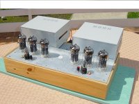
Here is an amplifier I built ( three units ) using three paralleled 6C33 and delivering 50 watts per channel, in Single ended topology.
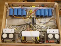
I attach the upper view and will follow with the view inside.
The power supply is in a separate box and connected with a simple twin wire cable.
The filament and driver transformers are on the main unit (the one shown). THD at full output is 6.5 % - Range 35Hz to 35 kHz
at -3dB .
You can find schematics and full description on AudioXpress magazine, July 2004.
Uses quite expensive OPTs .
Cheers,
Attachments
Very sorry,
I must read the threads more carefully.
Thanks for the comment.
Personally I never had the chance of using the 50, but I know it has a wonderful reputation.
By the way, is there a means to classify the valves by reputation ?
Of course this is not necessarily strictly correlated with quality.
Surely those who have a wide experience have some words to say.
It's probably a bad idea. Forget it.
Thanks again.
Ari.
Bonjour Ari,
Your humility is very impressive; I have watched your designs for a long time, Ari, and they are very, very creative, indicating to me at least a fundamental understanding of music........
I was always very impressed with your phase splitter using an EL84 from so long ago - lateral thinking!
And your 6C33C amplifier is impressive; your clever way of using a bipolar power supply is highly unusual. I have a couple, and would like to do something with them. For these low mu tubes do you think there is any advantage in driving the OPT in the cathode circuit rather than the plate? It would surely give a much lower turns ratio, and improve the damping factor?
Cheers,
Hugh
Hello Dean,
Very kind of you, I am very pleased, needless to say.
Your suggestion looks, at first sight, like an improvement.
In fact the swing required does not change, if the multipurpose load resistor of the driver valve is connected between cathode and grid of the corresponding output tube.
However, please check if that means ( I suspect ) to use monoblocks or separate drivers for each channel, instead of a common power supply for same.
Thanks a lot again.
I would be pleased to follow the results.
Ari Polisois
ari.polisois@wanadoo.fr
Nice amp ari
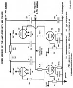
Here's what i have come up with based on my readings from Thorsten's post.
Due to power transformer limitation (will be using an existing Lundahl), I will be operating the 50 at 350V/-50/50mA/1K which I think will have enough juice to drive my Altec speakers.
Here's my mock schematics - not yet complete by any means, and I'd appreciate your input.
What are the candidates for the Plate and Grid chokes? What should be their specs? Would like to try some Hammond iron for these.
I also plan to use a VR tube 0C3 to provide ~190V for the 5842(417A) but since two 0C3 will yield 210V, can I use a dropping resistor to bring it down to 190V?
Thanks for any input.
Attachments
Konnichiwa,
Anode load Chokes:
S&B Anode Load Choke (120H/12mA 40% Nickel Core)
Tango TC160-15W (160H/15mA)
Magnequest EXO01 (100H/20mA)
Tribute (Custom made - if you are patient - Amorphous Core)
Grid Chokes:
S&B Grid Choke (4KH+/0mA 80% Nickel Core)
Magnequest BCP-16NI (1KH++/0mA ??% Nickel Core)
Magnequest BCP-16M6 (1kH+/0mA M6 Steel Core)
Tribute (Custom made - if you are patient - Amorphous Core)
You could also employ a 1:1 interstage transformer, to mind come:
Tango NC-20
Tango NC-16 (connected 1:1)
Tango NC-14
Tamura B-6003 (connected 1:1 - Amorphous Core)
Tamura B-5003 (connected 1:1 - Amorphous Core)
Audio Note Trans-016
James should have some nice IT's
Lundahl LL1635/20
Tribute (Custom made - if you are patient - Amorphous Core)
Sowter 8424
Sowter 9525 (maybe, Bifilar winding often gives bad sound)
The S&B Anode Load Chokes I had designed for myself where specified as 120H/12mA/1k2Ohm with a 50% Mu Metal Core (as a result total 40% Nickel). They turned out to have a little more inductance than that, they where meant as funtional equivalent to the Tango TC160-15W.
Given that you will have around 400V HT Available you could of course also use a 100nH (or therabouts) Choke with 15K DCR, in other words a nice 15K Resistor, in the 417A Anode, especially as you only need to drive 50V Peak. A 15K load for a 417A to drive 50V peak is pretty decent.....
In that case a 3K3 +B decoupling resistorwill be needed to get the 185V.
The S&B Gridchokes probably have a well, well oversized core for their own good and measure at ludicrous inductances (4.8KH @ 20Hz with a few volt excitation) and have 1K DCR, but a few more KOhm will not be of concern. Any of the above gridchokes will be fine, but with an original #50 in the output IT or GC grid returns are sadly mandatory.
I don't think Hammond has much suitable stuff.
A trick you can apply, find an Interstage transformer that has enough inductance (i'd say 50H minimum) and the current handling, no need to worry overly over HF response. Then bridge primary & secondary with a suitable capacitor like here:
Bob D used the Allied Electronics #227-0862 IIRC.
http://www.alliedelec.com/catalog/pf.asp?FN=681.pdf
I'm not sure if I would use that Transformer though. There might have been a technical report in one of the Valve backissues, I'll have a look. Then again, quite a few Joe-list members have been swearing by them....
Found the Valve back issue on the first try (dem old grey cells seem still to work, clearly not enough drink), they note the Allied IT as having 35H @ 12mA/60Hz, quite possibly tolerable, if not great. The poor HF response if dealt with with bridging cap (mixed coupling), leave chassis space for a Tango NC-20 if you like the results... ;-)
Sayonara
arnoldc said:What are the candidates for the Plate and Grid chokes?
Anode load Chokes:
S&B Anode Load Choke (120H/12mA 40% Nickel Core)
Tango TC160-15W (160H/15mA)
Magnequest EXO01 (100H/20mA)
Tribute (Custom made - if you are patient - Amorphous Core)
Grid Chokes:
S&B Grid Choke (4KH+/0mA 80% Nickel Core)
Magnequest BCP-16NI (1KH++/0mA ??% Nickel Core)
Magnequest BCP-16M6 (1kH+/0mA M6 Steel Core)
Tribute (Custom made - if you are patient - Amorphous Core)
You could also employ a 1:1 interstage transformer, to mind come:
Tango NC-20
Tango NC-16 (connected 1:1)
Tango NC-14
Tamura B-6003 (connected 1:1 - Amorphous Core)
Tamura B-5003 (connected 1:1 - Amorphous Core)
Audio Note Trans-016
James should have some nice IT's
Lundahl LL1635/20
Tribute (Custom made - if you are patient - Amorphous Core)
Sowter 8424
Sowter 9525 (maybe, Bifilar winding often gives bad sound)
arnoldc said:What should be their specs?
The S&B Anode Load Chokes I had designed for myself where specified as 120H/12mA/1k2Ohm with a 50% Mu Metal Core (as a result total 40% Nickel). They turned out to have a little more inductance than that, they where meant as funtional equivalent to the Tango TC160-15W.
Given that you will have around 400V HT Available you could of course also use a 100nH (or therabouts) Choke with 15K DCR, in other words a nice 15K Resistor, in the 417A Anode, especially as you only need to drive 50V Peak. A 15K load for a 417A to drive 50V peak is pretty decent.....
In that case a 3K3 +B decoupling resistorwill be needed to get the 185V.
The S&B Gridchokes probably have a well, well oversized core for their own good and measure at ludicrous inductances (4.8KH @ 20Hz with a few volt excitation) and have 1K DCR, but a few more KOhm will not be of concern. Any of the above gridchokes will be fine, but with an original #50 in the output IT or GC grid returns are sadly mandatory.
arnoldc said:Would like to try some Hammond iron for these.
I don't think Hammond has much suitable stuff.
A trick you can apply, find an Interstage transformer that has enough inductance (i'd say 50H minimum) and the current handling, no need to worry overly over HF response. Then bridge primary & secondary with a suitable capacitor like here:
An externally hosted image should be here but it was not working when we last tested it.
Bob D used the Allied Electronics #227-0862 IIRC.
http://www.alliedelec.com/catalog/pf.asp?FN=681.pdf
I'm not sure if I would use that Transformer though. There might have been a technical report in one of the Valve backissues, I'll have a look. Then again, quite a few Joe-list members have been swearing by them....
Found the Valve back issue on the first try (dem old grey cells seem still to work, clearly not enough drink), they note the Allied IT as having 35H @ 12mA/60Hz, quite possibly tolerable, if not great. The poor HF response if dealt with with bridging cap (mixed coupling), leave chassis space for a Tango NC-20 if you like the results... ;-)
Sayonara
Dear Arnold,
Your schematics looks OK.
Please rectify the stated drop at the 1k2 bias resistor. In fact
if the plate current is 0,050 Amps, you have V = I x R =
0,05 x 1200 = 60 Volts ( and not 50 , as I read on your schematics).
The dropping resistor for ( before ) the two 0C3 in series should be 1667 ohms ( 1k5 - 5 W would do ).
Thornsten answered on the plate and grid chokes. You have a lot of choices.
According to the SE Amp CAD simulation, with the ONE Electron UBT2 transformer, you would get 4,65 Watts , with a B+ of 450 V
( can you make it with your power tranny ? ) , with a 2nd Harmonic distortion of 3,7 % and a third H. Dist. of 0,1 % .
Damping factor 2,8 . You need a swing of 60 V PEAK ( circa 43 Vrms). Plate current would be 49,5 mA.
If you can't reach this B+ voltage, try with 390 V, and you can get the same results, but you should use a fixed bias supply of - 60 V,
positive to ground and negative connected to the low end of the grid choke ( previously disconnected from ground ).
However, the style 50 tube manufacturers advise to use self-bias.
Should you wish to switch to a DCMB circuit (Sorry, but I have to promote my own circuits), let me know and I will convert yours into one. You will need to use a 6SN7GT instead of the 5842, but you will save the plate and grid chokes and you won't need an interstage tranny.
Bye
Ari.
... you will save the plate and grid chokes and you won't need an interstage tranny.
Sounds like a steal of an audio deal!
ari polisois said:Tom,
Would you be kindly more explicit to an Italian living in France that is willing to understand everything in English, but obviously does not master all proverbs and sayings ?
Thanks.
Yes, Ari, if I'm not cryptic, I'm using slang! I meant to suggest that your circuit solves certain problems in an elegant way that, to a person shopping around for an interesting circuit, represents an excellent find. Just my opinion.
Thorsten, thanks as always. I will see if I can get hold of those transformers that you recommended. The simplest for me is to use the Lundalh IT which I can get from Singapore.
Ari, how can I refuse? I also would like to learn, so please feel free to convert it to a DCMB circuit with explanations if you don't mind? Thanks!
I am a just a builder
ps. the 1k2 should have been 1K
Ari, how can I refuse? I also would like to learn, so please feel free to convert it to a DCMB circuit with explanations if you don't mind? Thanks!
I am a just a builder
ps. the 1k2 should have been 1K
- Status
- This old topic is closed. If you want to reopen this topic, contact a moderator using the "Report Post" button.
- Home
- Amplifiers
- Tubes / Valves
- I'd like to make a simple 50 amplifier