This may seem a very stupid question.. but my knowledge is limited and i want to be sure.
I am building two Icepower 125ASX2 amplifiers and I have a question about the wiring in BTL mode figure 17 in the data sheet (see attachments).
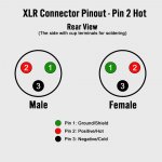
Does the little triangle (-1) means that Vin Channel 1 is to be connected to the Negative (3) on the XLR connector (see Attachment).
The longer I look at it the more I doubt, so a conclusive answer would put me out of my misery..
R.
I am building two Icepower 125ASX2 amplifiers and I have a question about the wiring in BTL mode figure 17 in the data sheet (see attachments).
Does the little triangle (-1) means that Vin Channel 1 is to be connected to the Negative (3) on the XLR connector (see Attachment).
The longer I look at it the more I doubt, so a conclusive answer would put me out of my misery..
R.
Attachments

If you have symetric audio source, you can connect ch1 to hot point and ch2 to cold. To works, the BTL needs 2 signals with 180deg dephasage.
The small triangle in the ICEPower diagram indicates Inversion ... For a Bridge Tied Load to work you need two signals 180 degrees out of phase so that one amplifier is going positive while the other is going negative with identical signals... the speaker is then connected across the positive speaker poles.
There are a number of ways to achieve this. The best is with a dedicated phase splitter built into the same chassis as the amplifier board.
You can also cheat as @riritronic has suggested. It will work, but you may lose some of the noise immunity of the balanced/differential output of your dac. Pin 2 to left channel, Pin 3 to right channel, Pin 1 to ground.
In my opinion, since your DAC has balanced outputs you have the chance here to upgrade to "Balanced Audio" and it's advantages, so you might want to look for or build an appropriate interface card for your project.
Last edited:
Hi Douglas,
I don't mind to cheat but I do like to doing it right, do you have an example of such a interface? R.
I don't mind to cheat but I do like to doing it right, do you have an example of such a interface? R.
There are commercial boards for this, I'd take a look around on some of the better suppliers like Amazon or Parts Express to see what I could find.
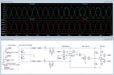
The attachement is a quick lash up (i.e. untested) of an XLR receiver and BTL driver. I've also added a gain control, which you might find useful.
The Top set of traces show the input, I've added some noise bursts to show how XLR, used properly, can clean up a noisy signal.
The bottom set of traces show the output... ready to drive the ICE Modules with nice clean signals.
Of course you will need to build 2 receivers, use a stereo gain control and 2 BTL drivers for Stereo.
For the convenience of the simulation I've set R5 and R6 to 0 ohms. In use they should be about 1 or 2 ohms.
Now be warned... this is a lash up, not a proven circuit. You probably should build it on proto board first, make any adjustments to get it working then build a proper version of it from there.
I've included the LTSpice file, if you want to run your own sims.
Attachments
Last edited:
Hi Douglas,
Thanks for your reply, for now this is a bit to complicated for me. So first I will cheat and look into your solution while listening to my build. Thanks again..
R.
Thanks for your reply, for now this is a bit to complicated for me. So first I will cheat and look into your solution while listening to my build. Thanks again..
R.
If your pre amp is symmetrical, you do not need to use it in an asymmetric way and then use an additional stage to make it symmetric again. Your signal does not get better from another hand full of op-amps switched in between.
Just go direct from your pre into the ICE amp, one half with hot, the other with cold, ground if desired. Don´t forget to set the BTL sync jumper.
The picture you posted, from the ICE manual is for an asymmetric signal source, where another inverting stage with gain 1x has to be used. This is not your case.
Ah! Thank you for your explanation. I will go ahead with the build as you described.
Sure thing ... it will work nicely. The only drawback is, no gain controls, but that's not a big problem so long as you have a volume control somewhere before it.
I would suggest you do need to hook up the grounds. You are likely to get a fair bit of hum if you don't.
Last edited:
I am doing the same...question where does the ground wire go to from the board? It seams like it is redundant since the board is grounding it to the chassis too. I am not an electrician, and a friend of mine is wiring it for me.
Does the 3rd pin on the XLR get hooked up too or is it left unused? If it is to be hooked up...where does the 3rd wire on the XLR go to?
Does the 3rd pin on the XLR get hooked up too or is it left unused? If it is to be hooked up...where does the 3rd wire on the XLR go to?
Last edited:
- Home
- Amplifiers
- Class D
- Icepower 125ASX BLT Question