I'm upgrading the op-amp in my cd player's analog stage, and I'm wondering if I should use an IC socket with it, in case I want to swap later.
Does anyone know how IC sockets perform in terms of adding noise or corrupting signals?
Does anyone know how IC sockets perform in terms of adding noise or corrupting signals?
Using a socket is a very good idea if your going to be experimenting.
There are the best quality sockets (gold-plated turned pins)
and the more common not so good sockets.
IMO the best quality sockets will form very good and reliable
connections the first few times they are used, ideally a proper
IC insertion tool should be used.
I don't know what will happen if the socket is re-used a lot.
🙂 sreten.
If you're going to use sockets, be sure to use the turned pin ones.
They look better, it's easier to install IC's in them, give better contact, don't cost that much more, ...
They look better, it's easier to install IC's in them, give better contact, don't cost that much more, ...
If you do this, it can make sense to fit 2 sockets on top of each other, and use the topmost, replacing that when it becomes troublesome. That way the one soldered to the board get less use, and does not need to be replaced.
But it all depends on how much swapping you intend to do.
But it all depends on how much swapping you intend to do.
This response is a little late, but the original question was not really addressed, so:
IC sockets will increase the swept area between signal lines and ground. The effects of nearby electric fields (esp from digital signals or AC) will increase as you increase this area.
Additionally, the IC socket will add inductance on all pins and capacitance between pins. This is on the order of nH and pF (fairly small). It will cause the opamp distortion to increase, but with small gain configurations it's probably not noticeable.
A hand waving explanation: inductance is added to all the pins, inductance means delay, opamps work in a feedback configuration, more delay in the feedback loop is going to give you distortion.
One (high quality) socket is probably fine, if there are no digital signals nearby. That said, stacking two IC sockets together, as Havoc recommended, will probably give you a noticeably deleterious effect as opposed to mounting directly on the board.
Maybe you could get a tiny little ZIF socket (if they actually exist) like the kind used on an eprom programmer.
A hand waving explanation: inductance is added to all the pins, inductance means delay, opamps work in a feedback configuration, more delay in the feedback loop is going to give you distortion.
I think you vastly over estimate the added values of sockets! We use sockets in uprocessor circuits with busses running at 100MHz, at it continues to work. So the loads are very small.
IMNSHO most distortion of opamps today comes from output stages not able to supply current. In lots of distortion measurements, the antique NE5532 comes out above as it can hold its spec while supplying current to loads of 1k and lower. While most modern amps their distortion goes off the graph anco the load drops below 50k.
if it isn't socketed already, don't add a socket -- mount the device "dead bug" style (i.e. with its feet sticking up in the air) on the bottom of the printed circuit board. just push the pins onto the traces and tack down. this will minimize trace lengths and it will be pretty easy to remove if you don't like the effect.
Havoc, I think I did too (overstated effects of distortion due to added inductance). And your point is well taken that which op-amp is chosen will far outweigh the socket, or lack thereof. However, that a socketed part "works" in the digital world is of course no testament to the effect it might have on nearby analog circuits.
A socket will increase the loop area susceptible to B-fields, which proportionally increases the induced voltage (Faraday's law). And it's pretty noisy inside most consumer electronics devices. Two sockets, of course, doubles the noise. Is the noise significant?
(some math below concludes it is)
Assume a digital signal with a rise-time of 2ns, into 10pF, with a swing of 5V. The instantaneous current (I=C*dv/dt) is 25mA. Now, ground planes are sometimes hard to come by in cheap products, so let's say this trace runs over 2cm of bare board. By the Biot-Savart law (a special case of Maxwell) the magnetic field at a point (our socket) 10cm from the center of the trace is 10nT.
(for perspective, B-fields in the average home are 100-500nT, but most of that is varying at a leisurely 60Hz).
10nT seems small but remember this field is being created and destroyed in just 2ns (dB/dt=5T/s). Faraday's law states that the voltage induced in a loop is proportional to the rate of change of the magnetic flux. How big is our loop? A standard DIP socket adds 0.4cm of height to the chip. A DIP package is 0.8cm wide. We'll use this rectangle. The EMF induced in this loop is, applying Faraday's law, 160uV.
1 LSB of a 16-bit DAC into a full scale of 2V (line out level) is 30uV. Let's say for safety that I was off by a power of 10, that's 16uV or 1/2 LSB of noise . I'm not even counting E-field noise, which is where 60Hz pickup will happen. Keep in mind this noise is in addition to the noise (due to the same flux) that would exist without the socket.
Now, even if all my math is correct, I admit there's still hand-waving in my favor: I've assumed the loop in the socket is parallel to the interfering trace, I've assumed the loop impedence to ground is high, I've assumed certain geometries and electrical characteristics in favor of making a point (but not, I think, outside of reason). I think the proverbial horse is dead now. My conclusion: no sockets.
By the way, I welcome a second opinion on the math. Just google for Biot-Savart's law, and Faraday's law, it's quite straightforward.
You are correct about loops etc. But most people forget that an important factor in the induction (electrical or magnetic) is the impedance of the receiving end. Now I don't know about every circuit, but if you like low noise, then you design low impedance. Meaning you work with feedback resistors <10k, even much lower if you can get away with it.
So I think that if you do not feel sure soldering and unsoldering, then a socket is worth it. And if you are going to plug in several tens of times, 2 sockets might be a good idea.
As risetimes in digital circuits, I did some measurements couple of weeks ago, and even in low speed circuits (+/- 20MHz) you find rise times in the order of <1ns. It takes some planning to get them measured accurately, but once you are that far, it surprises you each time. Not to mention the over and undershoots.
Whats the difference between turned pin sockets and regular ones?
Could somebody explain this or possibly post some pics?
Thanks
Could somebody explain this or possibly post some pics?
Thanks
"turned" means machined. Machined sockets are higher quality, better for multiple insertion cycles. As opposed to regular, stamped metal sockets, which tend to destroy the pins on your part after a couple insertions.
Machined sockets have round pins, stamped sockets have rectangular, stamped pins.
Here are some machined DIP sockets:
(pdf link)
Machined sockets have round pins, stamped sockets have rectangular, stamped pins.
Here are some machined DIP sockets:
(pdf link)
PCB Layout
Hi all
Looking at the layout of the components surrounding the opamp in my CDP, it appears that they are spread quite far apart and connected by long traces.
Can the introduction of a socket really make any significant difference by increasing the length of these traces by such a small amout - relatively?
What is likely to happen if you move the opamp to a separate board and construct an identical, but less widespread, circuit around it? The opamp would be further from the main PCB and groundplane but closer to its decoupling caps etc?????
Sometimes when reading postings on this board I wonder where all the fancy explanations and postulations come from,- other than shere speculation............??
I just measured the pin-to-pin capacitance on a good quality socket,- my C-meter shows nothing- zero-... with .1pF resolution. In RF work one assumes an inductance of 10nH pr.meter of straight wire, - hence the extra max 4mm from using an IC pin should amount to ca. 40 pH..............surely there are both C and L, but probably in the order of a few pH's and some femto-Farads. Compare that to your PCB track lengths, and you have an answer....
For the earth's field introduction and effect on wires,--- the earth field has a total B component ( directed towards the center) of 50-60 uT, - not nT, depending on where you are one the globe...
Fin- you can probably safely use sockets for testing...but use good quality, - not the cheap singel wipe version. The main problem with sockets is increase of contact resistance over time, maybe also with corrosion effects to the contacts. The main reason to avoid sockets are reliability over time, - in that light you better avoid them, but for testing they are quite OK, - that is of course, if you're not a devoted member of the paraphysics club !
Thanks for the reply
So, I might use a couple of gold plated (for corrosion resistance), turned pin sockets until I have made a final decision on the opamps.
What do you think of buiding a new, small board for the opamps, with point to point wiring and a good connection to the main groundplane?
The surrounding circuit could be constructed more concisely on the new board.
Originally posted by AuroraB
Fin- you can probably safely use sockets for testing...but use good quality, - not the cheap singel wipe version. The main problem with sockets is increase of contact resistance over time, maybe also with corrosion effects to the contacts. The main reason to avoid sockets are reliability over time, - in that light you better avoid them, but for testing they are quite OK, - that is of course, if you're not a devoted member of the paraphysics club !
So, I might use a couple of gold plated (for corrosion resistance), turned pin sockets until I have made a final decision on the opamps.
What do you think of buiding a new, small board for the opamps, with point to point wiring and a good connection to the main groundplane?
The surrounding circuit could be constructed more concisely on the new board.
For testimg over a limitedtime, corrosion should be no problem, unless you surround yourself with all kinds of strange acidious fumes........
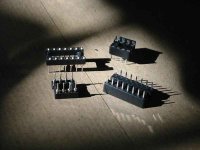
The sockets at left above are quite OK, but by all means,- if it makes you feel better, use the gold plated ones.
It is quite strange though, this negative vibes for sockets...
I do agree they should be avoided in the long run, but for short time testing.- no problem. As I said, it is contact problems, mainly associated with cheap sockets, that gave these little gizmos their bad reputation, and not without reason. OTOH, we do use connectors, relays, wires etc. to hook up pre to power, transistors heatsink/boards etc. All these introduces C's and H's as we go along. After all, your signal chain starts with your source and ends at the loudspeakers. We all agree that the shortest route possible is the ideal way to go, to minimize line lengt etc.etc. but logic and reason is allowed, - and so is common sense.
Thanks again for the advice
Didn't select "gold plated" out of choice - but it is the only type of machined ones available in the local electronics store - apart from the real cheap "swipe" ones which nobody seems to like. Besides, the better quality ones are also inexpensive - only AUD$1 each!
The sockets at left above are quite OK, but by all means,- if it makes you feel better, use the gold plated ones.
Didn't select "gold plated" out of choice - but it is the only type of machined ones available in the local electronics store - apart from the real cheap "swipe" ones which nobody seems to like. Besides, the better quality ones are also inexpensive - only AUD$1 each!
From Altronics catalogue
Contact Resistance: 30m? Max @ DC 100mA
Insulation Resistance: 1000M? Min @ DC 250V
Current Rating: 1 Amp
Dielectric Voltage: AC 500V for 1 Minute
Operating Temp: -55° to 105° C
Gold Plated Beryllium Copper Contacts.
- Status
- Not open for further replies.
- Home
- Source & Line
- Analogue Source
- IC sockets and noise