For a coaxial cable (Belden 1694F) of typical 1 to 2 meters long used for unbalanced interconnection, the capacitance ranges from 53pF to 106pF and the inductance ranges from 348nH to 696nH. The resonant frequencies range from 18MHz to 37MHz. The characteristic impedance is 75R.
So if we were to terminate the interconnect cable, at the preamplifier output (say opamp output) we would use a 75R resistor alone, and at the power amplifier receiving end we would use a series 75R and some C to shunt to ground.
The question is how much C is suitable?
Bob Cordell recommended terminating interconnect cables with some RC with C=100pF at the input of an amplifier.
I did just that. But now looking at the TDK capacitor impedance chart, I found that 100pF has a resonant frequency much higher than the cable resonant frequency. So would 100pF be sufficient? It looks like 100pF won't work in the frequency range of 18-37MHz.
For a 1 meter cable with resonant frequency at 18MHz, 10nF has a resonant frequency at around 18MHz. But if 10nF is used, although the RC -3dB roll off point is above 200kHz and is not of a concern, 150R/10nF would present a large capacitive load to the proceeding opamp stage and I don't know if 150R provides sufficient isolation.
So what is the minimum C that will work to terminate the cable properly without presenting too large a capacitive load?
(P.S. I was auditioning interconnect cables yesterday and each cable sounded different. It was very obvious and shouldn't be placebo effect. It drove me nut thinking how slight differences in LCR values could effect the sound by so much. I am determined to investigate that. I think the first thing is to try terminating the cables properly...)
I was auditioning interconnect cables yesterday and each cable sounded different. It was very obvious and shouldn't be placebo effect.
If that's actually true, your preamp needs a close look for stability.
You might want to look elsewhere, cable termination is irrelevant over the audio frequency range according to any electromagnetic theory I am acquainted with. Matching impedances is unnecessary and worse runs against all audio design conventions.(Most op-amps,etc are not designed to drive what could effectively be a 150 ohm load.) Your op-amp output should already have an output series resistor to prevent external capacitive loads from turning it into an oscillator, if it doesn't I would choose something larger than 75 ohms. (Say 220) You might look for instability driving capacitive loads. In "weak" output circuits notoriously CFs realized with 12AX7 and similar, the source impedance is high enough that cable interactions are possible due to cable capacitance, and possibly the DA/DF of the insulation used. I have heard some effects I attributed to these sources.
IMO this is not a good place to share your observations, feel free to PM me if you wish to discuss further.
IMO this is not a good place to share your observations, feel free to PM me if you wish to discuss further.
In analog audio devices, a low output impedance (600ohm) driving a high input impedance (50k) is the norm, and reduces the affect of any half decent IC to negligible.
If that's actually true, your preamp needs a close look for stability.
In the cable comparison session, it was done at my friend's system, not mine. The source was a Marantz UD7007. The output has 160R in series. The destination was a NAD 302 integrated amplifier used as a preamp. The power amplifier was a Moon by Simaudio. The Loudsepakers were a pair of B&W801.
When I mentioned I was worried about the capacitive load I was referring to my own line level preamp / active crossover which I use OPA627 to buffer the output (with 75R in series at the output), and my LMOSFET power amplifier with which I used 75R/100pF at the input as Bob Cordell recommended.
I have lately found that even mild resonance well above audio frequency affects the sound. It gives some colourations to the sound changing sound perception.
For now I don't look beyond LCR and shielding for an IC. I don't believe in magic.
When I was using a 150MHz 2mV scope operating in batteries to look at the input of my preamp, I found some resonances in the tens of MHz region. The same resonance was found elsewhere. In the end, I found that if I took out the Belden 1694F IC cables I made, the resonance disappeared. Put the IC back on (when the proceeding stage is not powered) the resonance came back.
So I am guessing that if ICs sound different they may possible resonate at different frequencies hence producing different colourations. Of course, my knowledge is limited so I could be all wrong.
Your op-amp output should already have an output series resistor to prevent external capacitive loads from turning it into an oscillator, if it doesn't I would choose something larger than 75 ohms. (Say 220)
In analog audio devices, a low output impedance (600ohm) driving a high input impedance (50k) is the norm, and reduces the affect of any half decent IC to negligible.
Unfortunately, my power amp feedback has an impedance of a parallel of 270R and 10k. In order to match the input impedance and the feedback impedance in the LTP I must keep the series resistance to 270R in total and can't go over that.\
Actually, that is actually irrelevant because if I follow the "proper RC termination" I would need a fairly low R (70R to 100R) and a C which will present as low impedance at RF to the proceeding opamp.
Last edited:
A coaxial cable can be terminated to reduce reflections at the cable ends.
The Source should feed through a series resistor into the coax core. This resistance plus the output impedance of the Source should equal the characteristic impedance of the cable.
At the Receiver end of the cable the load between core and shield should be a resistance equal to the characteristic impedance of the cable. This resistor will load the source at all frequencies. Cordell shows us how to remove the audio frequency load but retain the vhf/uhf loading for those potentially troublesome RF reflections. Add a series R+C as the load at the Receiver end.
Just put the roll-off high enough to not impinge on the audio bandwidth, i.e. >=200kHz.
10nF & 75ohm has F-3dB =212kHz.
But you could use 4n7F, or 2n2F, 1nF
Last edited:
What resonance?HiFiNutNut said:The resonant frequencies range from 18MHz to 37MHz.
No. This is an audio interconnect, and at audio frequencies the characteristic impedance of a '75ohm' coax is most definitely not 75R - it will be higher, frequency dependent and reactive. I guess he is talking about an RF termination. I can see some sense in doing this for a speaker cable, but not an interconnect. It will get some back-termination from the source impedance anyway.So if we were to terminate the interconnect cable, at the preamplifier output (say opamp output) we would use a 75R resistor alone, and at the power amplifier receiving end we would use a series 75R and some C to shunt to ground.
A 1m coax will typically have a quarter-wave resonance at 50MHz.For a 1 meter cable with resonant frequency at 18MHz
100pF does not have a resonance frequency. A particular 100pF capacitor will have a resonance frequency, depending mainly on the lead length (which you determine). It behaves as a capacitor for all frequencies below the resonance, so it is good that the resonance is high.But now looking at the TDK capacitor impedance chart, I found that 100pF has a resonant frequency much higher than the cable resonant frequency.
I think you need to understand what you are doing before starting to calculate. Then you may find that you don't need to do anything.So what is the minimum C that will work to terminate the cable properly without presenting too large a capacitive load?
10nF & 75ohm has F-3dB =212kHz.
But you could use 4n7F, or 2n2F, 1nF
Thanks, Andrew.
But is 75R (source) -> 50pF (cable capacitance) -> 75R (receiver) -> 1nF still too large a capacitive load for the opa627? or the opa627 can comfortably handle it?
What resonance?
No. This is an audio interconnect, and at audio frequencies the characteristic impedance of a '75ohm' coax is most definitely not 75R - it will be higher, frequency dependent and reactive. I guess he is talking about an RF termination. I can see some sense in doing this for a speaker cable, but not an interconnect. It will get some back-termination from the source impedance anyway.
A 1m coax will typically have a quarter-wave resonance at 50MHz.
100pF does not have a resonance frequency. A particular 100pF capacitor will have a resonance frequency, depending mainly on the lead length (which you determine). It behaves as a capacitor for all frequencies below the resonance, so it is good that the resonance is high.
I think you need to understand what you are doing before starting to calculate. Then you may find that you don't need to do anything.
Thanks, DF.
The Belden cable has 50pF, 327nH and 2.6mR per meter. Using the formula f = 1 / (2 * pi * sqrt(L * C)) we get f = 39.4MHz. Suppose R = sqrt(L/C) then we have R = 81.
When I said the 100pF has a resonant frequency, I meant the crossing point that the inductive component of the impedance takes over. Below that point, the capacitor has higher and higher impedance towards lower frequencies. What I meant was that the 100pF may have too high impedance at 39MHz to be effective to be used in the RC termination of the cable.
Capacitor impedance vs frequency - one example can be found here:
Analog Devices : Analog Dialogue : PCB Layout
Obviously the 100pF has fairly high impedance at 39MHz.
Analog Devices : Analog Dialogue : PCB Layout
Obviously the 100pF has fairly high impedance at 39MHz.
Your persistent assumption that that RG59 coax, for example, has a characteristic 75R impedance is quite wrong for audio frequencies, as already stated. Neither the source or load will be near 75R either. Audio power amplifiers have typically 10-50k input impedance for unbalanced or somewhere near 600R when a balanced line input is included. A quality preamp has typically a 200R unbalanced output impedance but may be much higher or lower, depending on what the market expects at the price. Successful connections depend on those gross mismatches to avoid the complications of trying to match myriad products with only nominal terminal specifications.
RG59 cable impedance varies wildly from DC to daylight and considerably over the 3 or more decades of the audio band. That's why it's little more than fat, low cost shielded wire when used for audio leads.
http://audiosystemsgroup.com/TransLines-LowFreq.pdf
RG59 cable impedance varies wildly from DC to daylight and considerably over the 3 or more decades of the audio band. That's why it's little more than fat, low cost shielded wire when used for audio leads.
http://audiosystemsgroup.com/TransLines-LowFreq.pdf
That formula is for lumped elements. It gives the wrong answer for distributed elements, such as a transmission line. For a line you need to know the velocity factor (approx 0.8 for this coax?), and decide whether you are interested in the quarter-wave or half-wave resonance. For 1m of this cable the quarter-wave resonance will be around 60MHz.HiFiNutNut said:The Belden cable has 50pF, 327nH and 2.6mR per meter. Using the formula f = 1 / (2 * pi * sqrt(L * C)) we get f = 39.4MHz.
All you need (if you are worried about cable resonances) is some resistive termination to damp the resonance. You will already have some from the source, so the load does not have to be exact. It can't be exact anyway, as the input capacitance of whatever comes next will be in parallel with your CR network.What I meant was that the 100pF may have too high impedance at 39MHz to be effective to be used in the RC termination of the cable.
I don't worry about coax cable RF resonances when connecting audio circuits. This assumes, of course, that the source is not generating much RF and the load will largely ignore incoming RF and the cable is well screened so it won't pick up much external RF. If any of these is untrue then the solution is to fix the problem, not fiddle around with cable terminations in an attempt to hide the problem. Speaker cables may be different, as these are usually longer and unscreened.
Your persistent assumption that that RG59 coax, for example, has a characteristic 75R impedance is quite wrong for audio frequencies, as already stated. Neither the source or load will be near 75R either. Audio power amplifiers have typically 10-50k input impedance for unbalanced or somewhere near 600R when a balanced line input is included. A quality preamp has typically a 200R unbalanced output impedance but may be much higher or lower, depending on what the market expects at the price. Successful connections depend on those gross mismatches to avoid the complications of trying to match myriad products with only nominal terminal specifications.
RG59 cable impedance varies wildly from DC to daylight and considerably over the 3 or more decades of the audio band. That's why it's little more than fat, low cost shielded wire when used for audio leads.
http://audiosystemsgroup.com/TransLines-LowFreq.pdf
Thanks for your note and the article. It makes sense to me.
I have now remodelled the LC of the IC at low frequencies and found that provided that the preamp output has 120R or above there should be no resonance / peaking at the input of the power amp. My original 75R output impedance may be a bit low and there may be some peaking depending on the power amp input stage.
That formula is for lumped elements. It gives the wrong answer for distributed elements, such as a transmission line. For a line you need to know the velocity factor (approx 0.8 for this coax?), and decide whether you are interested in the quarter-wave or half-wave resonance. For 1m of this cable the quarter-wave resonance will be around 60MHz.
All you need (if you are worried about cable resonances) is some resistive termination to damp the resonance. You will already have some from the source, so the load does not have to be exact. It can't be exact anyway, as the input capacitance of whatever comes next will be in parallel with your CR network.
I don't worry about coax cable RF resonances when connecting audio circuits. This assumes, of course, that the source is not generating much RF and the load will largely ignore incoming RF and the cable is well screened so it won't pick up much external RF. If any of these is untrue then the solution is to fix the problem, not fiddle around with cable terminations in an attempt to hide the problem. Speaker cables may be different, as these are usually longer and unscreened.
Thanks for your comment. It is very helpful.
What would you do with speaker cables, other than the standard Zobel and LR output? Do you have a remote Zobel at the loudspeaker end? I am also thinking about screened speaker cables.
Nothing, unless I had reason to believe there might be a problem.HiFiNutNut said:What would you do with speaker cables, other than the standard Zobel and LR output?
I don't think you understand what you are doing. At audio frequencies (where the LCR cable model is OK) there cannot be any peaking from a 1m cable. At RF the LC model is no longer valid; you have to use a distributed model.I have now remodelled the LC of the IC at low frequencies and found that provided that the preamp output has 120R or above there should be no resonance / peaking at the input of the power amp.
Nothing, unless I had reason to believe there might be a problem.
I don't think you understand what you are doing. At audio frequencies (where the LCR cable model is OK) there cannot be any peaking from a 1m cable. At RF the LC model is no longer valid; you have to use a distributed model.
Thanks, DF.
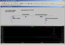
I am attaching a simplified model I used. So what you are saying implies that the 42MHz peak shown is not real because at that frequency it should be modelled as lump elements.
Attachments
If I read DF correctly
But you said
then at 47MHz you should be using the distributed model.At RF the LC model is no longer valid; you have to use a distributed model.
But you said
which is the opposite. This seems to confirmthe 42MHz peak shown is not real because at that frequency it should be modelled as lump elements
I don't think you understand what you are doing.
- Status
- Not open for further replies.
- Home
- Amplifiers
- Solid State
- IC Cable termination