'Sound is round', so the length would be a function of a sound 'bubble's diameter, but if using an expo flare (M = 1) the length will be dictated by its 'mouth' width and typically ~ a saw blade's ~1/16" (0.0625") width at its 'throat', so for a lower frequency slot for a given mouth/throat width a < M = 1 flare will be required with a hyperbolic (M = 0.5) being the practical limit AFAIK.
Obviously, more than one side can be slotted, allowing the flare to be divided up to form a rectangular version of fig. 1c: http://home.planet.nl/~ulfman/images/karlfreq.gif So I'd start with a slot on just the rear panel and space the BIB away from the wall a bit and if this isn't enough, then start lengthening downwards/expanding it around the sides with the understanding that its F3 will rise pretty much in lock step with increasing slot area, so I don't recommend using large increments when increasing mouth size/length.
Obviously, more than one side can be slotted, allowing the flare to be divided up to form a rectangular version of fig. 1c: http://home.planet.nl/~ulfman/images/karlfreq.gif So I'd start with a slot on just the rear panel and space the BIB away from the wall a bit and if this isn't enough, then start lengthening downwards/expanding it around the sides with the understanding that its F3 will rise pretty much in lock step with increasing slot area, so I don't recommend using large increments when increasing mouth size/length.
pjanda1 said:The spreadsheets I downloaded seem to require one to know the target length and width from the get go. How does one arrive at those numbers?
Kust go in and start playing. In the end you want an area. This is untired territory, so start small, you can always make the slot(s) bigger. GM posted an old article that he suggested would help in sizing the slot (i've downloaded it but not read it yet)
dave
edit: i see GM & i were typing simultaneously and he has come up with some helpful info (as is often the case)
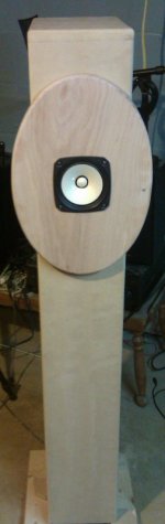
Been testing in mono using makeshift clamps.. So far I like it a lot. I'm using different drivers (widerange) that have very similar T/S as the FE127E with a slightly higher Fs of 75Hz. Scottmoose assured me it's theoritcally an okay 'drop in'.. It is.
No need for BSC to my ears. Bass is impressive even with not much density in lining/stuffing. Needs more listening test. I'm using twisted cat5 wiring for each terminal for now, it's ok but transients seem a bit blunted, will try other wiring soon...Sorry I don't have any equipment yet to do any measurements.
No need for BSC to my ears. Bass is impressive even with not much density in lining/stuffing. Needs more listening test. I'm using twisted cat5 wiring for each terminal for now, it's ok but transients seem a bit blunted, will try other wiring soon...Sorry I don't have any equipment yet to do any measurements.
Attachments
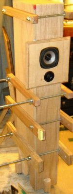
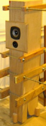
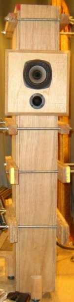
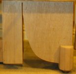
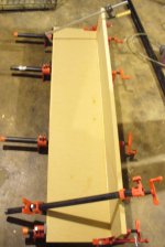
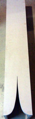
.. half of K-slot on one side. the curve doesn't look as smooth in the pic than it actually is. sorry all of it was hurriedly shot. To size the slot a friend did the calcs in Tractrix spreadhsheet for me that can be downloaded from the Karlson site. The are ~27"^2 area was used as suggested in planet10's published plans.
Attachments
hi fred76 - how did you inverted bibK end up playing vs RCA-Fans' k-slot 8" blh? did the shape d-Q or not? Best, Freddy
freddi said:hi fred76 - how did you inverted bibK end up playing vs RCA-Fans' k-slot 8" blh? did the shape d-Q or not? Best, Freddy
Hi Feddy,
I haven't had the chance to directly compared the two... The Lowther drivers I have on RCA-fan's backhorn test have been shot for some time now (damaged surrounds). I didn't have access to good quality void-free ply back then. If I were to do it again and had better quality plywood, I'd double the ply material to 1.5" for the external walls and use real wood for the braces that runs down in the middle. I would've also used Sonic Barrier from PE inside the back chamber directly behind the driver, experimenting with various thicknesses available.
Anyway, WRT the ~5" driver I-BIBk, the slot was already in place when the testing was done... It would be interesting to hear from someone who also built I-BiBk's and directly compared 'em with and without the K-slot.
FWIW, I am quite satisfied/impressed with the mid-bass response of both designs. Obviously though, the larger drivdrs in RCA-fan's design have the advantage of better LF BW and efficiency... I don't have any measuring devices like RTA etc. so everything is subjective.
regards,
fred
Hi Fred76, nice iBIBk.
I built one using Fostex 127e a couple of years ago, and it sounds great, bass is amazing.
I am bringing it to the Alabang Audio Show, August 8-10, do you want to bring yours and exhibit on the DIY room?
I built one using Fostex 127e a couple of years ago, and it sounds great, bass is amazing.
I am bringing it to the Alabang Audio Show, August 8-10, do you want to bring yours and exhibit on the DIY room?
Has anyone had any luck in developing a solid formula for calculating a Karlson slot yet? I've read about a Excel file on this thread. Can anyone send it to me? Lots of the old links in this thread no longer work.
Just finished preparing my suprabaffle for staining.
Before I had the suprabaffle finished, I temporarily installed the speakers into the cabinets without the suprabaffle. Just a basic 4" hole in the front of the cabinets, with correct height on center according to the plans.
Before I glue the suprabaffles on, I'm wondering if I should enlarge the driver hole from where I installed the Fostex drivers before, effectively removing area behind the suprabaffle piece. From Dave's iBiBk Google Sketchup rendering, it looks like there's a larger square cut, but someone suggested I could leave the driver hole the same size as-is. Though, maybe there's a bit of "interaction" from the back of the driver from the thickness of the wood behind the suprabaffle? Maybe not, but thought I'd ask before I glue!
Since the whole idea of the BIB backline is to attenuate anything above a few hundred hertz, and the back hole will only effect frequencies above 1khz, I can see absolutely no benefit in enlarging the hole.
Shoog
Shoog
Since the whole idea of the BIB backline is to attenuate anything above a few hundred hertz, and the back hole will only effect frequencies above 1khz, I can see absolutely no benefit in enlarging the hole.
Shoog
Thanks! Now that I'm thinking about it... I forgot to chamfer the back of the driver hole. I still have the opportunity to do that with the suprabaffle, so maybe I should enlarge the original cutout. However, if the back isn't very affected by the same size hole in the first place, then chamfering doesn't seem like it'd be very essential.
I'm wondering if I should enlarge the driver hole from where I installed the Fostex drivers before, effectively removing area behind the suprabaffle piece.
Yes you should. The back of the sB driver hole should also be opened up (we use a 45 degree bevel) and the hole on the baffle should be at least a continuation if not larger.
Pictures?
dave
Yes you should. The back of the sB driver hole should also be opened up (we use a 45 degree bevel) and the hole on the baffle should be at least a continuation if not larger.
Pictures?
dave
Sure. Here are pics of the temp cutout, the suprabaffle stacked on top of the original baffle, and the baffle and driver fitted. I haven't glued the suprabaffle yet. I still need to smooth out the baffle cutout. I cut the hole out with a jigsaw. Didn't have a circle router jig yet. Helpful accessory!
Attachments


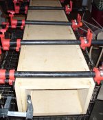
Here are a couple more pics of the assembly. It took me a long time. This is the 3rd set of enclosures I've ever built. The first being when I was about 10 years old and the enclosure fell apart under its own weight.  I guess I've progressed somewhat since then. 🙂
I guess I've progressed somewhat since then. 🙂Attachments
Looking good. You do need to releive the backside of the cutout or you will have a really cuppysoundfrom the tunnel. I'd dramatically open up the baffle hole, and the backside of the sB needs a bevel.
dave
dave
Looking good. You do need to releive the backside of the cutout or you will have a really cuppysoundfrom the tunnel. I'd dramatically open up the baffle hole, and the backside of the sB needs a bevel.
dave
Will do.
Hi there: GM states ( post #121, 9 SEP 07 ): ...understanding that F3 will rise in lock step with increasing slot area...
Does this mean: to apply the K slot, you need to over design the bass response of the enclosure so that when the K slot is applied the F3 will end up where you intended it to be in your origional "requirements"? ...regards, Michael
Does this mean: to apply the K slot, you need to over design the bass response of the enclosure so that when the K slot is applied the F3 will end up where you intended it to be in your origional "requirements"? ...regards, Michael
- Home
- Loudspeakers
- Full Range
- iBIBk developement thread.