iBiBk and 2001 monolith
So I've got the 2001 monolith going with Hemp Acoustics FR8C's. I was wondering if I covered the top (which would be the previous terminus), added a 1/2 Karlson slot to each side, just how well this would work. I only have 1 back wall and a 10-foot ceiling height to load against, and I need to keep the enclosures right up against the wall (save the 1/2" trim piece about 10" from the floor on the wall.
So I was thinking since it was mentioned in this thread that the slot can be split into half and made on each side, that I would still be able to push the enclosures against the wall. Also, depending on their size, I wouldn't need to raise the enclosures and won't need to make a bottom opening. Is this correct?
Hopefully some folks are still following this thread. 🙂
Greets!
Yes, you can do this, but understand that it will have a higher F3 due to shortening its acoustic path-length. Whether this matters much with a BIB once the room gain is factored in, I'm not sure. Anyway, with 10 ft ceilings, why bother?
GM
Yes, you can do this, but understand that it will have a higher F3 due to shortening its acoustic path-length. Whether this matters much with a BIB once the room gain is factored in, I'm not sure. Anyway, with 10 ft ceilings, why bother?
GM
planet10, can you elaborate more on the suprabaffle in your iBIBk PDF?
I am not sure how to make it. A circle seems a bit more obvious but an oval might need a little approximating with a jigsaw and a bit of sanding. I'm not sure how great this approach is, however.
I also don't fully know why a suprabaffle works. I was looking at some of your other posts from a year or two ago with the Olson graphs of various shapes and baffle diffraction. I didn't see anything about an oval as used here. I also was looking at http://t-linespeakers.org/tech/bafflestep/index.html and determined that from these two sources, a sphere, or at least a circle is a really good shape for a baffle.
Finally, I'm confused as to why the fill-in suprabaffle pieces are used behind the suprabaffle. Perhaps they complete the rounded area of the suprabaffle to more closely mimic a sphere shape.
Thanks in advanced.
P.S. your graphic designs are inspiring when looking for something to build next.
mrbubbs said:I am not sure how to make it. A circle seems a bit more obvious but an oval might need a little approximating with a jigsaw and a bit of sanding.
I also don't fully know why a suprabaffle works. I was looking at some of your other posts from a year or two ago with the Olson graphs of various shapes and baffle diffraction. I didn't see anything about an oval as used here. I also was looking at http://t-linespeakers.org/tech/bafflestep/index.html and determined that from these two sources, a sphere, or at least a circle is a really good shape for a baffle.
Finally, I'm confused as to why the fill-in suprabaffle pieces are used behind the suprabaffle. Perhaps they complete the rounded area of the suprabaffle to more closely mimic a sphere shape.
A circle would be fine. A square would be fine. Etc. An ellipse just spreads out the distance from the driver to the edge. A supraBaffle pushes the frequency at which baffle step happens down in frequency... if it gets low enuff it can then hand off to a rear or front horn with more than unity gain, or with room gain, so as to acoustically battle bafflestep.
In the iBIBk the size of the supraBaffle is a SWAG.
If you look at the Olson graphs you will see that one of the worst shapes is the driver mounted on the end of a cylinder. This is what a flat circular baffle is. By rounding off the edges and by adding a trainling edge we push the circlular baffle closer to a sphere.
Olsen never made an elipsoid (in those days they actually had to build it and measure it), it is as good a shape as a sphere, maybe better. Look to the research B&W did to come up with the shape of the midrange pod in the Nautilus.
dave
By making the baffle "not" perfectly circular you distribute the frequency which is effected by the edge effect over a wider range. A perfect circle will produce a definite dip at the frequency at which the baffle effect disappears.
I use a circular baffle but mount the driver off centre in the baffle.
Shoog
I use a circular baffle but mount the driver off centre in the baffle.
Shoog
I think I'm on my way to understanding this. I'm pondering making the area where the driver meets the baffle contoured to further approach an ellipsoid.
For anyone else interested, a few sites I found with useful baffle step / diffraction loss are:
http://t-linespeakers.org/tech/bafflestep/index.html
http://www.trueaudio.com/st_diff1.htm
The frequently referenced original research for this seems to be
Harry F. Olson's article "Direct Radiator Loudspeaker Enclosures".
While I was looking through the AES.org index, I noticed an available algorithm for "computing edge diffractions from an arbitrarily shaped planar baffle with a round piston source", named "Computation of Diffraction for Loudspeaker Enclosures" by J Backman. This seems useful to me, if I can avoid guessing. Though others have said the process is more tweak and listen.
Now I only have to decide if I want to split the Karlson slot in half so I can push the enclosure right against the wall or stick with the original design with the box pulled out into the room a bit.
mrbubbs said:While I was looking through the AES.org index, I noticed an available algorithm for "computing edge diffractions from an arbitrarily shaped planar baffle with a round piston source", named "Computation of Diffraction for Loudspeaker Enclosures" by J Backman.
Thanx for that. I head Juha deliver that paper but for the life of me couldn't gind it... Svante's Edge takes this further (son't know whether it is based on the same algoritms)
dave
mrbubbs said:Now I only have to decide if I want to split the Karlson slot in half so I can push the enclosure right against the wall or stick with the original design with the box pulled out into the room a bit.
When we get around to ours it will be the former.
dave
Just so I am doubly sure before I waste any wood...
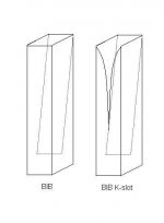
If splitting the Karlson slot in half to put on each side of the enclosure instead of just the back, what does the shape look like? Would the cut just not be as tall? I assume the shape has to be the same, as that's the whole reasoning behind the slot and how it's calculated.
Thanks in advanced.
If splitting the Karlson slot in half to put on each side of the enclosure instead of just the back, what does the shape look like? Would the cut just not be as tall? I assume the shape has to be the same, as that's the whole reasoning behind the slot and how it's calculated.
Thanks in advanced.
mrbubbs said:Just so I am doubly sure before I waste any wood...
If splitting the Karlson slot in half to put on each side of the enclosure instead of just the back, what does the shape look like? Would the cut just not be as tall? I assume the shape has to be the same, as that's the whole reasoning behind the slot and how it's calculated.
Thanks in advanced.
For half a Karlson slot, drop a line vertically from the point to divide the slot in 2... same height, the side facing the wall is the straight line you used as a bi-secter, and the curved part is one side of the whole slot.
dave
Hello all !
it's been a while since I visited full-range !
Good to see y'all thinking of implementing a K-slot in a Voigt or BIB
last year I build a pair of Voigt pipes using a K-slot at the bottom.
It seems to me the extra gain in the bass region comes in more
gradual using an exponential slot as opposed to just a square hole.
The normal hole is more like an "on/off" device; as bass goes deeper,
the extra gain comes in at a certain point.
K-slot seems to blend that point
But as I understand the theory of K-slots, thats not the intention of
an exponential slot in a pipe. It's about killing the odd harmonics of the
frequency at wich the pipe resonates.
Wouldn't the proper use for the benefits of an exponetial slot be like in
an organ pipe ? e.g. at the back, to 2/3 length of the pipe ?
Cheers,
Empee
Attachments
Well, that was certainly Karlson's original intention for the design (yet another great British idea that never recieved the funding it needed) There's no 'proper' use for anything though really -if it works for achieving a different purpose, then great. 😉
Yup, you're right 🙂
But indeed the idea was to kill odd harmonics of the freqency at wich the pipe resonates.
But do we want the pipe to resonate at all ?
or is it we want the pipe to resonate at more than just one freq. ?
But indeed the idea was to kill odd harmonics of the freqency at wich the pipe resonates.
But do we want the pipe to resonate at all ?
or is it we want the pipe to resonate at more than just one freq. ?
The only graph I have of a K-slotted lioe is for Roger Sander's Speaker Builder 3 meter t-line loaded with Eclipse W1038R. There wasn't much polyfill in the line.
The K-slot had double the area of the rectangular vent. I didn't have any wood scrap so cut the curve down to the existing vent so it probabaly came out with too much area. I wish iI had thought of turning the cabinet on its side to see how that affected the plot versus standing upright.
Modified line
http://img214.imageshack.us/img214/256/ktlle9.jpg
Response outdoors with W1038* (~20Hz fs) polycone 10" woofer
http://img176.imageshack.us/img176/7710/kslottline1038rhf2.gif
subjectively this T-line loaded with Eminence Beta 10CX sounded better, smoother with the K-slot although comparison might be difficult unless input Z was adjusted to be about the same for both conditions.
it might be a good idea to make removable panels to adjust the slot to taste
Greets!
No, you don't want to 'kill' its harmonics, but instead make them all equal amplitude with the fundamental without resorting to using any stuffing, i.e. a broad band (low Q) resonator. With a BIB you have both even and odd harmonics, so the K-slot should in theory make an even smoother response if done properly, with 'properly' meaning it must be a lot longer/bigger for a given Fc (Fp). Also, due to the lower pipe loading, in theory a higher effective Qts will be desirable.
GM
http://members.aol.com/klehma/karlson.html?mtbrand=AOL_US
and
http://home.planet.nl/~ulfman/
I got those from the iBiBk drawing from planet10 found earlier in this thread.
and
http://home.planet.nl/~ulfman/
I got those from the iBiBk drawing from planet10 found earlier in this thread.
Empee said:Hi!
Does anyone have a calculator for K-slots ?
cheers,
Empee
I built the iBIBk as drawn by Planet10 using Fostex 127e.
I can't believe the bass coming out of the 4.5" Fostex driver on this enclosures.
As for the Karlson slot, I used 11-1/4" high half slot on the side and raise the speakers by 1.75" off the floor.
I will experiment with the height of the opening at the bottom of the speakers and post my findings.
Overall, my iBIBk is better than my my Wharfedale Evo10 and my old Acoustic Research S40, better vocals and highs and quite tight bass.
An externally hosted image should be here but it was not working when we last tested it.
I can't believe the bass coming out of the 4.5" Fostex driver on this enclosures.
As for the Karlson slot, I used 11-1/4" high half slot on the side and raise the speakers by 1.75" off the floor.
I will experiment with the height of the opening at the bottom of the speakers and post my findings.
Overall, my iBIBk is better than my my Wharfedale Evo10 and my old Acoustic Research S40, better vocals and highs and quite tight bass.
- Home
- Loudspeakers
- Full Range
- iBIBk developement thread.