@ernesternest,
On the metallic area in the middle of the LT3042 package outline, yes, you need to get that soldered to the thermal pad on the bottom of the LT3042. So you need to use solder paste there and make sure it gets to temperature.
I do mine mostly by hand. I use a thin-gauge solder to tin the thermal pad on the bottom of the LT3042 package and also on the board. I also tin 2 opposite-corner LT3042 pin pads. I then use solder wick to remove MOST of the tin from these areas. On the solder pads. I leave a perceptable amount, but not so much that there is any noticable bulge.
Then I carefully align the LT3042 chip on the board, making sure to get pin 1 in the right location, and hold it down with a very tiny flat head screwdriver. I then use a VERY fine tip soldering iron to attach those opposite-corner pins to secure the LT3042 package to the board. To ensure I have them aligned correctly, I solder one AND make sure it is aligned well with the pads on that side, then nudge the LT3042 package if needed to get the other side's pads/pins aligned before soldering that side.
Before going forward, I again confirm the pins are lined up with the pads on the board and adjust if needed. Use magnification here if needed... I have to!
Then I use my solder-rework heat gun to first heat the bottom of the thermal pad area, then flip the board over and hold the LT3042 in place with that fine-tip screwdriver while heating the package top. I use a 30-count on the bottom of the board and a 24-count on the top.
After that cools, I remove the screwdriver and inspect again to confirm the pins are still aligned with the pads AND that the LT3042 package is firmly flush against the board.
If alignment issues at this point, I will use the rework hot-air gun to remove the LT3042, discard it, and start with a new one. I've done a LOT of LT3042/LT3045 soldering (maybe 50-75 devices!) and always buy 1-2 spares for every 4-8 packages I need to install.
Only then do I solder the remaining pins.
THEN before going forward, I use a VERY fine tip probe and check continuity on each pin. I use the fine probe so I can touch it to the small exposed pad area on the LT3042 package side and not the joint to make sure the joint is secure.
Then I solder on the rest of the components.
Note that it takes me about 2x-3x as long to do this (after doing a LOT of these) as it takes you to read to this point! Practice!
@wlowes, thanks for catching @ernesternest's question!
@wlowes, my take now is that Ultracaps will be a benefit if using regular supplies as you are (and thanks for your reporting on this), but likely less so if using direct-connected batteries or full-Ultracap supplies (based on @supersurfer's reporting).
AND that as supplies, Ultracaps are at least equivalent to LiFePO4 and to my ears, superior. That is not a knock on the LiFePO4 supplies, they are VERY good too!
I'm hopeful that the larger-value SMD PPS caps will also provide a benefit even with Ultracaps or LiFePO4 direct power. Same with the Black Gates, but most won't have or be able to get them while the SMD PPS caps are currently available (though the 5uF-22uF in the Rubycon lines are pretty dear!).
@wlowes, I think you'd be safe using the 5.5V-rated Ultracaps on your +5V and -5V rails on your TDA1541A setup. As for the -15V supply, I suspect you want to have an active balancing circuit with that long (6 caps minimum) of an Ultracap string.
Greg in Mississippi
Thanks Walter, thanks Greg! What a comprehensive post. I will give it a try, probably today.
Cheers, Ernst
Cheers, Ernst
Mrdog uses ians lifepo psu to power his three dac rails, each has a 1.5f supercap on it. It sounds great, maybe a tiny bit better than just the three lifepo rails straight into the dac.
Mrdog uses ians lifepo psu to power his three dac rails, each has a 1.5f supercap on it. It sounds great, maybe a tiny bit better than just the three lifepo rails straight into the dac.
Which DAC model is in question?

Well, having a totally DCDC converter free 3b Pi, powered by ldovrs Mezzaninboard, which is powered by a LT1083, again powered by a 4A 6V transformer.
Another LT1083, at 5V powering the FifoPi, right side, and a TPS7A4700 regualtor powering the DUAL 9038 dac at 3.3V. The dac has got four small supercaps in place.
The standard I/V converter board has got 2xOPA1622 and 1xOPA1612 opamp in place and is powered by regulated by a discrete reg (reused from an old preamp).
I am pretty much surprised by this combination and currently it is difficult for me to imagine, what could get more amazing with the LT3042 regulators in place.
Having started yesterday the first 2 small pcbs were working right at the first test. But what a pain to solder!!! Especially the resistors R1 and R3 and the LED, which I cancelled. Since I am lazy, I only worked with my hot air gun and tried to reduce solder paste to the absolute minimum. This worked except the third reg was not working. It just show slow rising voltage at about 0,8V. Will check it today. Needed some break for my eyes.
Cheers,
Ernst
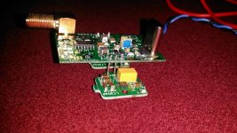
Could you take a picture of your small Ian canada reg pcb?
I find the schematic confusing compared to physical layout.
I find the schematic confusing compared to physical layout.
confusing reg
Jim, yes, actually a bit confusing. Resistor 1 and 3, if i remember correctly are so small, that their name print is done far away. More in the area of some C's.
I can make a pic later, or tomorrow, but have a look at the board. The tinyest parts are the resistors. They are unbelievable small and really hard to place. Btw, all the parts are hard to place.
Cheers, Ernst
Thanks....no rush. IIRC there were 2 components...maybe an R and a C thet were in parallel and shared a larger pad. But the silk screen and the schematic didnt show the same thing...although I am no expert at any of this!
In both cases the bigger parts are the C's. And somewhere close, or not too far away there are tinytiny solderpoints for the R's.
Attachments

Last edited:
Ah thanks Ernst....that clears that up nicely. I thought from the type on the board that r3 AND c2 went on those big pads.! Silly me
Hi Guys,
I just read in Ian 9038 dual mono doc that it supports up to dsd1024.
Did some of you tried to feed FIFO II and 9038q2m dual mono with dsd512(or more) signal using hqplayer for upsampling and some xmos216 for the usb to i2s?
What will be the best clocks frequencies for playing dsd512 with the less jitter?
Did some of you tried to feed FIFO II and 9038q2m dual mono with dsd512(or more) signal using hqplayer for upsampling and some xmos216 for the usb to i2s?
What will be the best clocks frequencies for playing dsd512 with the less jitter?
Tried that experiment with Ian's FIFO_Pi and with the big FIFO board (with the separate clock board). In the latter case, found problems with RF noise susceptibility that improved with putting the FIFO inside a steel case. Also found multiple problems with the reliability of u.fl connectors if removed and reinserted more than once or twice. The first time they installed, they have a bit of friction that can be felt trying to gently rotate them a bit in their sockets. After removing and replacing a connector once, already the friction is clearly less. As ground finger friction reduction happens, jitter performance rapidly declines, IMHO. A solid ground of RF cables is essential for any connectors in a high performance dac. Good quality SMA connectors are much, much better than u.fl for critical applications like keeping clock jitter low. Even then, SMA connectors may need to be lightly torqued with a small wrench to produce a good quality ground for RF. SMA coax cables also need to be good quality or jitter will also suffer from that.
Thus, I think FIFO_Pi would be my preferred choice for what you are talking about doing. Also, the same types of considerations that apply to u.fl connectors also apply to clock sockets. They loosen very quickly with repeated use, and they permanently loosen when thicker pins are inserted even one time. As a result, jitter can be adversely affected very quickly there too.
Wish I had better news regarding the above.
The good news is that using FIFO_Pi with a new u.fl cable to provide the dac clock, and with the various dac boards separated as I described before, the performance using a USB board to provide I2S into FIFO_Pi can work quite well. Ultimately, the most insurmountable problem that caused me to give up on it was the lack of full stereo AVCC separation in the dual ES9038Q2M dac.
Last edited:
Hi Mark,Tried that experiment with Ian's FIFO_Pi and with the big FIFO board (with the separate clock board). In the latter case, found problems with RF noise susceptibility that improved with putting the FIFO inside a steel case. Also found multiple problems with the reliability of u.fl connectors if removed and reinserted more than once or twice. The first time they installed, they have a bit of friction that can be felt trying to gently rotate them a bit in their sockets. After removing and replacing a connector once, already the friction is clearly less. As ground finger friction reduction happens, jitter performance rapidly declines, IMHO. A solid ground of RF cables is essential for any connectors in a high performance dac. Good quality SMA connectors are much, much better than u.fl for critical applications like keeping clock jitter low. Even then, SMA connectors may need to be lightly torqued with a small wrench to produce a good quality ground for RF. SMA coax cables also need to be good quality or jitter will also suffer from that.
Thus, I think FIFO_Pi would be my preferred choice for what you are talking about doing. Also, the same types of considerations that apply to u.fl connectors also apply to clock sockets. They loosen very quickly with repeated use, and they permanently loosen when thicker pins are inserted even one time. As a result, jitter can be adversely affected very quickly there too.
Wish I had better news regarding the above.
The good news is that using FIFO_Pi with a new u.fl cable to provide the dac clock, and with the various dac boards separated as I described before, the performance using a USB board to provide I2S into FIFO_Pi can work quite well. Ultimately, the most insurmountable problem that caused me to give up on it was the lack of full stereo AVCC separation in the dual ES9038Q2M dac.
Thank you for your answer.
Maybe Ian will make an upgraded board with proper avcc separation?
I will send him a pm about that.
I’ll maybe test this setup to try hqplayer that I never used before( I’m using moode audio on rpi)
I’m using 45/49 cchd 957 crystek with fifoPI, do you think it is ok for dsd512?
I too found it confusing initially. Study the pcb carefully before soldering. It will become clear where the parts go even though in some cases it is not possible for the label to be next to the part due to the small real estate.Could you take a picture of your small Ian canada reg pcb?
I find the schematic confusing compared to physical layout.
Attached is a pic that shows the parts placed on one of mine.
Attachments
Last edited:
I’m using 45/49 cchd 957 crystek with fifoPI, do you think it is ok for dsd512?
IIRC, they should fast enough for ES9038Q2M operating in synchronous or master mode with DPLL = 0. The dac chip needs to be clocked at twice the DSD clock frequency in that case. If in asynchronous mode then the dac clock needs to be at least 3 times the DSD clock frequency. DSD512 is normally clocked at 22.5MHz and is based on the 44.1kHz clock family. It is also possible to clock it a bit faster using the 48kHz clock family. HQ Player has settings for upsampling compatibility with either clock family.
IIRC, they should fast enough for ES9038Q2M operating in synchronous or master mode with DPLL = 0. The dac chip needs to be clocked at twice the DSD clock frequency in that case. If in asynchronous mode then the dac clock needs to be at least 3 times the DSD clock frequency. DSD512 is normally clocked at 22.5MHz and is based on the 44.1kHz clock family. It is also possible to clock it a bit faster using the 48kHz clock family. HQ Player has settings for upsampling compatibility with either clock family.
Thank you Mark.
I will give it a try.
- Home
- Source & Line
- PC Based
- IanCanada's Latest RPi GB Goodies Impressions... and your tweaks, mods and hints...