See the thread The Well Tempered Master Clock - Building a low phase noise/jitter crystal oscillatorMah i have some details on Andrea mori clock ?
The recent group buy for SC cut crystals from Laptech in Canada produced results in the range of 1ppm.
I implemented the Rasmussen filter as per Ian’s post #548 but the 1uf caps of the filter pick up RF noise. Does anyone have the same issue? The noise will be louder when use metal film cap than MLCC. Is there anyway to shield the I/V std?
I would agree, and an empty steel case from an old PC may be ideal for test purposes. Steel is much better at stopping RF than aluminum.
Mark, steel is actually inferior to Aluminium for RF shielding due to it's poorer conductivity.
Steel is much better for LF shielding of electro magnetic interference due to it's high permeability and as you would expect, materials like Mu Metal better again.
T
T,
Copper is more reflective, and steel is more lossy. One can make a copper RF shield that reflects RF away and or that allows RF currents to circulate on the outside, or to trap RF inside.
A thick enough piece of steel is also pretty good at keeping RF out, and tends to be more lossy for any RF that gets inside through wiring (rather than making a nice cavity resonator inside). If we do a good job of managing how wires get through the shield barrier, then copper in a given thickness is better for high frequency RF. If we don't do such a good job with managing how wires pass through the walls, then a stout steel case can actually do quite well over a fairly wide frequency range. 16ga or 18ga steel computer cases can be very handy for casual testing work, assuming steel doesn't cause problems with the circuitry. Since a computer case usually has a good amount of space inside, a dac can be positioned in the middle, well away from any of the walls. A steel case works quite well for that, and also well for finished products like Benchmark DAC-3 and AHB2.
On the other hand, for a close fitting can around a clock module, I would use copper, no question.
What frequency is your clock running at? Did you power the clock from lifepo4 battery? (I would expect so) I bought some andrea boards a long time ago, guess I should get around to putting it together.
Randy
He 3.3v is from battery, 6v not yet, I will change this to run from two batteries (6.6v)
Surfer, what caps did you run on the crystek?
I used the crystek on twisted pear conversion board, no extra caps added.
Hi Wlowes,Can you indicate what length and type of cable you used to connect the clock to FIFO? I am looking at low loss SMA 1 foot or less.
I used the 2” ufl cable from Ian. After the oven is ready and tested I want to try to put the clock directly on the fifopi.
I also have some bigger low freq sc-cut clocks that are waiting for the new driscoll board with separate squarer board from Andrea. I expect them to perform even better (lower phase noise).
Yes, Here are the schematics and assembly manuals:
https://www.diyaudio.com/forums/dig...itter-crystal-oscillator-151.html#post5073292
https://www.diyaudio.com/forums/dig...itter-crystal-oscillator-151.html#post5073292
I look forward to your experience with the 5mhz variant.Hi Wlowes,
I used the 2” ufl cable from Ian. After the oven is ready and tested I want to try to put the clock directly on the fifopi.
I also have some bigger low freq sc-cut clocks that are waiting for the new driscoll board with separate squarer board from Andrea. I expect them to perform even better (lower phase noise).
Clock direct connect has clear merit based on signal strength.
An alternate view that I am pursuing is to put the clock in a separate isolated chassis. Concept is to minimize vibration to the oscillator and to isolate noise from/to the oscillator.
Ok, thank you, I see now what I haven't seen before. BR, ErnstYes,
Here are the schematics and assembly manuals:
I believe there is room enough on the fifopi for one Andrea's direct crystal adaptator, so use the 44,1 Khz family crystal as this is what we 95% listen to. For the fifopi crystal area left one certainly can use for a oversampled 384 a crysteq with an acrylic smd, both directly soldered on the pcb to avoid any adaptators will be the best solution imho.
Hats solution have a default for dacs as it's like an antenna, better a flat design. As we have no choice, all those shielding without IME compatibility tools to measure is only speculation and I bet people whom will hear difference will be more victims of placebo effect.
I will bet on a decoupling and heavy solution for the fifo only in in a dac box, then steel around the power traffos to absorb its RF with a steel wall between the trafos and the pcb with the litliest holes for the power wires towards the pcb. Better several little hole at the size of each cable than a bigger one where all the cables will go to the pcbs.
Then have a wood cabinet with a layer copper shielding for the whole dac device. Don't forgett many litlle hole for cooling beter if those little holes because of RF are on the side of the power supply area that is already steel isolated and far from the pcbs.
Remember than the IME std are most of the time made and measured for a whole device not to pollute the others around.
Imho best clocks ennemies are first, antenna construction vs flat pcb design, too big pcbs and distance, mechanical then air vibrations... and maybe heat due to a too close shielding or boxing. Alllo has designed a cool Rpi box for its Kali streaming solution cause the aluminium box also manage the cooling by a coupling with the Rpi board.
Some cover their dac chip or crystal with a copper top with cooling paste and ground it to the close ground of the pcb but I suspect nobody knows if it's better or worse for IME without expensive measurement in the RF domain. Placebo ? Go figure...
Just my two cents, but my Andrea's 5 Khz will go direct on the fifopi if I cqn manage it and I greatly adice to use direct Andrea's adaptator made for the ancient Clock II board from Ian for your littlest sc cut case factor.
What we can see in DACs from Benchmark and others about shielding is more about IME compatibility norms for the US and CE marketts because their smps power supply. But yes they try to preserve the clock area like we often see with the brqnds clqiming ultra low pico jitter numbers.
Btw Supersurfer, what your first feeling about sc cut vs ndk or lapteq please? Subttle or game changer according your ears and more neutral ears from friends and family not involved as us in diy audio?
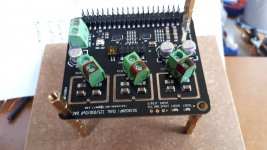
Anyone wishing to add 3 supply rails to the DAC could do so as this photo.
The connectors are a perfect fit across 'in' on the break out board and ground on the main PCB. The pins need a little filing, cut the 'in' track between main and break out boards. Remove 2 SMD caps.
The connectors are a perfect fit across 'in' on the break out board and ground on the main PCB. The pins need a little filing, cut the 'in' track between main and break out boards. Remove 2 SMD caps.
An externally hosted image should be here but it was not working when we last tested it.
Last edited:
Btw Supersurfer, what your first feeling about sc cut vs ndk or lapteq please? Subttle or game changer according your ears and more neutral ears from friends and family not involved as us in diy audio?
My reference is the standard clocks delivered with fifopi and the crystek CCHD-957 (on rhea pcb from tp).
The Laptech sc-cut is a game changer in my setup; more dynamics, better more defined low register, cleaner background, it is much easier to follow the decay of delicate sounds like a cymbal resonating and room acoustics.
This is without the oven and with temporarily linear ps instead of the battery for 6v supply.
I play with an interstage coupled directly heated triode amplifier with volume transformer to an open baffle wideband loudspeaker with high efficiency field coil drivers. My set is very dynamic and revealing. This makes it easy to hear improvements downstream(er)...
Your experience may vary depending on your setup.
Thank you Supersurfer for your feedback 🙂
I'm looking forward to see how I could adapt the brandnew discroll board from Andrea with the 5 Khz sc-cut I have. I wait to have its bom when finalized to buy also the parts from the previous discroll for some at-cut low frequency as well.
I'm looking forward to see how I could adapt the brandnew discroll board from Andrea with the 5 Khz sc-cut I have. I wait to have its bom when finalized to buy also the parts from the previous discroll for some at-cut low frequency as well.
Optional supercaps on dual 9038 dac?
Hi all - I've searched the thread but not found much. Anyone using the optional supercap positions on the underside of the 9038 dac board? Any experiences to share? If so, I'd be interested in which caps you used, what value (fair number of up to 4F horizontal type advertised in various places), what power supplies, and of course - what impact/effect on sound? Regards Adrian
Hi all - I've searched the thread but not found much. Anyone using the optional supercap positions on the underside of the 9038 dac board? Any experiences to share? If so, I'd be interested in which caps you used, what value (fair number of up to 4F horizontal type advertised in various places), what power supplies, and of course - what impact/effect on sound? Regards Adrian
My caps were above the board due to the clocks.
Avx 5v 2.5F 75mohms, mouser, 581-scms22c255mrba0
Or the similar 1.5F version with lower esr.
Just heat shrink the legs and bend the last 5mm over to put in the holes, out/gnd, after the mini boards.
Avx 5v 2.5F 75mohms, mouser, 581-scms22c255mrba0
Or the similar 1.5F version with lower esr.
Just heat shrink the legs and bend the last 5mm over to put in the holes, out/gnd, after the mini boards.
@misterdog
Can not see the picture
Ian
I think there could be an issue with the site, Google photos, or me.
I PM'd Adrian 311 with the link which worked, maybe someone could post a photo to narrow down the fault ?
I think there could be an issue with the site, Google photos, or me.
I PM'd Adrian 311 with the link which worked, maybe someone could post a photo to narrow down the fault ?
Here is the picture from misterdog.
Attachments
- Home
- Source & Line
- PC Based
- IanCanada's Latest RPi GB Goodies Impressions... and your tweaks, mods and hints...