Can I make one with instead of two of the same type transistors. say an NPN and PNP?
If so. how would I modify the circuit to accept it?
And how do i make it have a stable frequency with a strong output signal at like 60hz?
If so. how would I modify the circuit to accept it?
And how do i make it have a stable frequency with a strong output signal at like 60hz?
Last edited:
Why dod't you use the standard topology?
It's no problem to do it with npn + pnp. Any person, knowing the way transistors work, what the feedback is and how to calculate RC time constant can do it right away.
Is it some... school homework exercise? 😛
It's no problem to do it with npn + pnp. Any person, knowing the way transistors work, what the feedback is and how to calculate RC time constant can do it right away.
Is it some... school homework exercise? 😛
Can you give me a diagram? I dont know how to use feedback or calculate RC time constant but I can use a transistor as a transistor and put them together from a diagram. and build things from a switch to a small audio amplifier
do you know of or have any simple diagrams for making this?
I wanted to create a multivibrator or oscillator where output load doesnt affect frequency much but still gives good output power for the load.
and I chose a 40-50W NPN PNP transistor pair. and I have a 3-12V power supply. with capacitors and resistors and such
I wanted to power a transformer with a simple transistor inverter
if you dont have a diagram. how would I switch the 2nd NPN in the circuit for a PNP? all the diagrams i find have only NPN or only PNP for a multivibrator.
Last edited:
battery operated at 9-12V or using DC power supply.
I tried a silly experiment with a motor and piece of tape on the end of the motor blocking half of the shaft with 2 wires going in series with the transformer and the shaft and power supply... worked but barely.. and not very reliable either... i'd want something more reliable and that doesnt cause sparks to fly!
I tried a silly experiment with a motor and piece of tape on the end of the motor blocking half of the shaft with 2 wires going in series with the transformer and the shaft and power supply... worked but barely.. and not very reliable either... i'd want something more reliable and that doesnt cause sparks to fly!
Better to develop signal at low level and amplify.
Loading and temperature shift will change transistor characteristics...changing frequency.
Even crystal oscillators shift with temperature and loading. (slightly)
However,
If it is an AC motor then divide the RPM by 60 and that is the number of pulses that need to be applied per turn of the shaft...number of "pieces of tape"..not just one. (make a disc)
If you halve the number the motor should turn at half of the RPM.
Hope that helps.
🙂
i was simply using a DC motor to turn with a piece of tape on the shaft to generate the on/off with power in series between that and a transformer to transfer 9.5V to 120V but its a really inefficient design. rather than trying to use an AC motor.
I just had a thought... Doing that with an AC motor.. without the transformer.. You could effectively turn the AC motor into a DC motor..! wow
I am still in the dark as to WHY you would want to make your flip flop with different polarity transistors. A simple pair of the same type wired in two mirror image circuits cross coupled, et voila - oscillator.
I just had a thought... Doing that with an AC motor.. without the transformer.. You could effectively turn the AC motor into a DC motor..! wow
It is actually how most computer motors work for drives...a (or some) hall effect sensors sense the position of the magnets in the armature (spinning part) and send a synchronized signal to the drive coils.
It is what I thought you were trying to build.
I'm still wondering why any kind of oscillator is is up for posting in the Solid State power amplifier forum. Don't we try to eliminate oscillation here? 😀
We have to know the enemy 😀
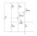
Realflow, this is an option, giving you roughly 60Hz pulses. Pulse width will not be 50%. If you want symmetric pulses, there are many ways to do it - with the same type of transistors, fixed logic elements, op-amps, etc.
Still not clear why you need npn+pnp there 😕
Realflow, this is an option, giving you roughly 60Hz pulses. Pulse width will not be 50%. If you want symmetric pulses, there are many ways to do it - with the same type of transistors, fixed logic elements, op-amps, etc.
Still not clear why you need npn+pnp there 😕
Attachments
NPN and PNP is all I have. I only have a pair of 1 PNP and NPN but no two NPN or two PNP's and since they are 40-50W each i thought it'd work perfectly..
How much output power will this circuit have? Can it drive a transformer 9.5V to 120V and power a CFL bulb? (like for emergency purposes if im stranded somewhere and need a light source or emergency power if the power goes out temporarily?)
If not. how would I modify the circuit to have more output power? Trying various designs like a BJT with negative resistance oscillator to have as a reference pulse generator at close to 60hz to turn on the base of a darlington power NPN transistor didn't seem to work out for me. it just made the output full on. and stopped the oscillation..
Last edited:
Sorry for another post (cant edit) but could I modify this circuit to get it to work?
http://www.talkingelectronics.com/projects/BasicElectronics-1A/imagesP2/Fig32 - PNP-NPN-Osc.gif but if not how would i make it have more power? or more stable frequency?
http://www.talkingelectronics.com/projects/BasicElectronics-1A/imagesP2/Fig32 - PNP-NPN-Osc.gif but if not how would i make it have more power? or more stable frequency?
Ive had an idea. is it possible to make an oscillator or pulse generator out of a string of diodes in series with a capacitor and resistor similar to how you'd use a transistor with collector and emitter reversed? or would that not work the same? since I thought diodes turn on after a certain voltage? or is that only how much voltage is lost when a voltage is applied?
but wouldn't that mean if you tried to apply a voltage lower than that. it'd drop all the voltage?
but wouldn't that mean if you tried to apply a voltage lower than that. it'd drop all the voltage?
Non of this is very practical for a beginner. To make a power oscillator that can drive a transformer with the aim of producing a specific output voltage (to run a CFL) is not easy. If you had all the transformer specs (not just the primary/secondary voltages) then it might be do-able as a one off design project and with a lot of trial and error.
The other problem is that running even a 10watt CFL of say 120 ? vac rating is going to need quite a substantial battery to power the thing. A diy oscillator like this is going to be hugely inefficient running a standard transformer.
Diodes alone can not make an oscillator (at least not the sort of diodes and sort of oscillator we are talking about here)
I found a 12v 0v -12v to 120V power transformer with a center tap out of an old powered subwoofer amplifier that has high power ratings would it work better?
How would I wire up a multivibrator circuit to accept an NPN and PNP rather than only PNP or only NPN?
How would I wire up a multivibrator circuit to accept an NPN and PNP rather than only PNP or only NPN?
Last edited:
Its not that easy I'm afraid. The waveform from a simple oscillator driving a transformer will most likely be a mess of harmonics and hash, its not going to be anything sine like.
Dugs suggestion of amplifying a low level signal is much better but non of this is practical for a battery power light.
I used to play around for hours with stuff like this as a youngster, and while its easy to generate high voltages from simple invertors (even one transistor invertors using the other winding for feedback) they are hopeless for what you are trying to achieve.
ive found some diagrams of multivibrator circuits that are used in an inverter but how would i swap out one of the NPN's with a PNP? since all i have is one NPN and one PNP right now.
- Status
- Not open for further replies.
- Home
- Amplifiers
- Solid State
- I want to create a transistor multivibrator.