What works surprisingly well is a 4017 CMOS chip directly driving a pair of IRFZ44's and transformer. Almost no heat. Set the 4017 to repeat a count of 0,1,2,3. Clock about 400 Hz with whatever you can find. Use the 0 and 2 or 1 and 3 to drive the FETs. That will produce 90 degree conduction angles, which has close to the right peak to average ratio and totally prevents cross conduction, even with reactive loads or poor layout parasitics. It will very efficiently run a 2x40W shop light fixture off a gel cell, and a boom box, and even small hand tools.
If you did use an SMPS driver chip, you could vary the dead time from 50% down to near zero to compensate for dropping battery voltage. But that's certainly not as simple and foolproof.
If you did use an SMPS driver chip, you could vary the dead time from 50% down to near zero to compensate for dropping battery voltage. But that's certainly not as simple and foolproof.
right now i'm only using some normal power NPN transistors and it seems to be working decently.
The output voltage definitely drops a bit. and the frequency is a bit too low. about half what it should be.
but that might just be how the transformer was made. causing it to be a lower frequency than maybe a smaller transformer.. Only way to increase frequency would be to use tantalum capacitors and different resistor values.. but it would reduce the actual output power possible..
I was thinking of buying some simple 100ohm 10W resistors off amazon for a more reliable output power..
I have four 1K 1/2W resistors (2 in parallel for each transistor) for only 500ohms.
i'd think using lower value resistors would have a lot more output power. i'd have to test that to see.. maybe the transistors would run cooler being closer to fully on and fully off. rather than off then partially on..
Maybe a more stable output voltage?
Using a diode and a small motor on the output of the transformer only runs it about same speed as if hooked directly to the power supply..
much of the current capability isnt there.
Last edited:
What works surprisingly well is a 4017 CMOS chip directly driving a pair of IRFZ44's and transformer. Almost no heat. Set the 4017 to repeat a count of 0,1,2,3. Clock about 400 Hz with whatever you can find. Use the 0 and 2 or 1 and 3 to drive the FETs. That will produce 90 degree conduction angles, which has close to the right peak to average ratio and totally prevents cross conduction, even with reactive loads or poor layout parasitics. It will very efficiently run a 2x40W shop light fixture off a gel cell, and a boom box, and even small hand tools.
If you did use an SMPS driver chip, you could vary the dead time from 50% down to near zero to compensate for dropping battery voltage. But that's certainly not as simple and foolproof.
y
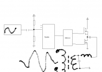
another option is to use sinewave oscillator, push the sine into tl494's 3 or 4 pin (dc biased) -> ir2111 -> mosfet bridge (half or full) (6 or 12V transformer) -> active lpf -> sinewave inverter 🙂
tl494 must be single ended output ctrl. (wider range of duty cycle)
another possib -> lm393+timer555 instead tl494
its possible even with only 555.
try to plug your on battery, it will empty the battery for a moment 😀
This solution will not produce heat at all !!
Attachments
Last edited:
I just found out the frequency is even lower than I thought... I used the sound of the transformer ticking
seems around 16-30hz at best.
Is there a way to get the frequency way way up?
and could I use a 12v solar panel to power it off the grid? That way we'd have emergency power for an eternity.
seems around 16-30hz at best.
Is there a way to get the frequency way way up?
and could I use a 12v solar panel to power it off the grid? That way we'd have emergency power for an eternity.
use class d and a sinewave if you want to power it from a solar panel and there must have an accumulator because solar panel is not powerfull, its only for charging. 

Is there a way to get the frequency way way up?
Drive the transistors at the intended frequency and not rely on self oscillation. It's the next logical step.
use class d and a sinewave
That's about 10 logical steps ahead. Not for someone just starting out in electronics. Unless you're talking about just using one of those Sure amp kits.Which would work of course.
It about halfway lights up a 29W incandescent bulb but after 15 seconds of use. with the transistors being warm.. the output sharply drops off and the transformer makes a whining noise.
Then the transistors get hotter faster. Sometimes one or the other.
It seems unbalanced temperature wise. causing issues.
Ive changed the transistors to darlingtons with some 2N3904's and changed the resistors to 10K's and it works great when powering a reactive load.
but poor when powering a resistive load like an induction motor or light bulb
(CFL's brightly light up. then transformer whines for a second. then it stops whining and the cycle repeats)
Neither the TIP35's or the 2N's are actually "HOT" but just reasonably warm.. They shouldn't be even close to breakdown temperature.. but it seems to be enough that it affects how they react with the transformer sadly.
Last edited:
Drive the transistors at the intended frequency and not rely on self oscillation. It's the next logical step.
dont rely self osc /!\
google -> "darlington saturation voltage"
Is it possible using a smaller transformer might be better? i've read that higher frequency would help with powering CFL lights and have more efficiency
and smaller transformers would have a higher frequency
Could I try that?
And if I dont have a center tap transformer could I take two identical transformers.
parallel the outputs. then take the inputs and put them in series? and use the middle as a center tap? Or would that not work?
also if you had a 470uF 10,000v capacitor and charged it to 6v does it have 6v with 0.0000001uF or something? or 6v with 470uF?
or if it was charged to 1v would it be 470uF at 1v? or even less capacitance?
does the capacitance stay the same at any voltage level till the voltage is 0? or does the capacity scale equally with voltage down from rated voltage?
Last edited:
If you don't have a center tap it won't work. Period. You need both halves of the cycle on the same core to balance the DC flux.
Smaller transformer = higher oscillation frequency. A 3" OD 2000-ish perm ferrite ring was giving me about 500 Hz. You're really supposed to use a tape-wound core for that, but the ferrite worked and didn't get hot 🙂. And supplied about 200 watts to the amplifier.
Capacitance doesn't scale with voltage. Charge (Q) does.
oh...
the transformer im currently using is really poor in frequency.. very visible flickering on the power strip surge protector light
Interesting if I take one of the base leads off. the frequency massively increases but it has really poor amount of actual power.
normally it barely even gets warm with no load or any load.
if there is too much load the frequency suddenly massively increases and the output power drops
but its capable of running my stereo amplifier at ear shreddingly loud volumes without cutting out.
Dude, try the class D sh*t.
Try to make an inverter with class d amp and you will be amazed.
if you want try 4017, its very better than yours, but class d is amazing.
REAL sinewave @ the out and NO HEAT and MAXIMUM POWER EFF and EASY AS YOURS
Try to make an inverter with class d amp and you will be amazed.
if you want try 4017, its very better than yours, but class d is amazing.
REAL sinewave @ the out and NO HEAT and MAXIMUM POWER EFF and EASY AS YOURS
how would I do that?
I dont think I have quite enough components to create that.
i only have a few 1k's 10K's and a few 4.7uF 50v capacitors
and a few NPN and PNP 2N3904/2N3906 types
I dont think I have quite enough components to create that.
i only have a few 1k's 10K's and a few 4.7uF 50v capacitors
and a few NPN and PNP 2N3904/2N3906 types
Where are you that you cant buy components ?
i'll draw a sch for u if u want.
or i can give u some links.
or i can give u some keywords.
pick up ur poison.
i'll draw a sch for u if u want.
or i can give u some links.
or i can give u some keywords.
pick up ur poison.
Where are you that you cant buy components ?
You could be in the richest most technologically advanced country in the world an not be able to buy components. Try living on a minimum wage job and going to school. In that case it's use what you have or can scrounge for free. It's amazing the sheer volume of stuff I was able to scrounge for free back in the 80's and early 90's. None of which could be used to make a class D amp at any meaningful power level and wouldn't explode the instant you put the screws to it. But it did make for creative use of low voltage power transistors to make real watts to DJ with, high power electrochemistry equipment (which made a lot of people nervous), and even that CMOS counter-based inverter which lit and powered building our tree fort on the university campus.
the most expensive thing is the ir2111 mosfet driver which is 1.5$ here. 
Look @ this -> http://www.aliexpress.com/item/2-x-..._7&btsid=a4cd2dfd-31f9-4432-8b71-e1a1576633e5
6$ Class d 2x50W , you could use it for music too ;p
one hit, two points =)
to my country the shipping is free, i do not know to yours.
i think im going to buy one to see quality and compare with mine.
Last edited:
- Status
- Not open for further replies.
- Home
- Amplifiers
- Solid State
- I want to create a transistor multivibrator.