Welcome to the forum, ljm.
I think I looked at the pinouts of a 2n5551, but posted a link to the correct cc5551 datasheet. It shows a different pinout, and that would make q2 & q4 a current mirror.
Sorry, my bad.
I think I looked at the pinouts of a 2n5551, but posted a link to the correct cc5551 datasheet. It shows a different pinout, and that would make q2 & q4 a current mirror.
Sorry, my bad.
Welcome to the forum, ljm.
I think I looked at the pinouts of a 2n5551, but posted a link to the correct cc5551 datasheet. It shows a different pinout, and that would make q2 & q4 a current mirror.
Sorry, my bad.
This is not your mistakes, because the transistor is rare.
This is not your mistakes, because the transistor is rare.
It's nice to have the designer's input, thank you.
Which is the best sounding amplifier, the MX50 or the MX50X2? I bought the MX50X2 because of its 4 output devices.
It's nice to have the designer's input, thank you.
Which is the best sounding amplifier, the MX50 or the MX50X2? I bought the MX50X2 because of its 4 output devices.
MX50X2 originated in MUSICAL FIDLITY MF-XA50. Is a very distinctive, good circuit.
MX50 circuit similar, but output using low distortion CFP circuit.
The two are very stable, and very convenient production.
MX50X2
Hi ljm, I've just built the MX50X2 and it sounds very good. Just wondering if it's possible to reduce the gain of this amp, the rest of my kit has to have the gain turned right down when driving it to produce reasonable listening levels.
Thanks
Hi ljm, I've just built the MX50X2 and it sounds very good. Just wondering if it's possible to reduce the gain of this amp, the rest of my kit has to have the gain turned right down when driving it to produce reasonable listening levels.
Thanks
Change the value of R7 (as in the post 39 schematic) to 27k. If it's still too loud, up the value of R9 to 1k2 or 1k5 or 1k8 or whatever works for you.Just wondering if it's possible to reduce the gain of this amp, the rest of my kit has to have the gain turned right down when driving it to produce reasonable listening levels.
Thanks
Last edited:
Change the value of R7 (as in the post 39 schematic) to 27k. If it's still too loud, up the value of R9 to 1k2 or 1k5 or 1k8 or whatever works for you.
Thank you ingenieus, I'll try your suggestions as soon as time permits.
Hello. I am very bad speak english, i am from Russia. bought the same kit. one channel is working fine, and when you turn on the second channel, the quiescent current in the arm + shows 0.82 A and is not regulated. may suggest what could be the problem. Thanks in advance.
Hello. I am very bad speak english, i am from Russia. bought the same kit. one channel is working fine, and when you turn on the second channel, the quiescent current in the arm + shows 0.82 A and is not regulated. may suggest what could be the problem. Thanks in advance.
Have you adjusted the bias potentiometer? If you have tried already and there was no effect on the current, check the pot resistance varies on a DVM.
i think the problem is only the preamplifier and the 5401 and 555thing stage
if i would have(d) time i would replace them with some higher waTage transistors
and of course again the calculations
Rihanna - Te Amo - YouTube
if i would have(d) time i would replace them with some higher waTage transistors
and of course again the calculations
Rihanna - Te Amo - YouTube
MX50 100W + 100W
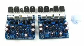
I built the same amp - however the modules I bought off Ebay were pre built and tested.
I'm not sure if the circuit diagram I posted is correct for the modules I have - but it was the one published on the auction page.
Details here is anyone is interested.
Mine is running at a lower power, as I'm using a 35-0-35 Vdc supply.
Any verdict on sound quality yet?
Any verdict on sound quality yet?
It sounds absolutely superb.
I currently have access to several power amps, Harman Kardon HK870, NAD2200 (very modified),Rotel 850 - and it beats them all, hands down.
It's very detailed, and the bass is simply superb too.
Source is Marantz CD17 (modified), Cambridge Azure DAC Magic, Ebay "Big DAC", and Logitech Squeezebox Duet.
Decrease gain
About MX50-SE(v7), I have a question, please:
I want to decrease the gain to 20 ~ 25 times for use in multi amplification for treble and mid range. What are the values and the resistors need to change?
thank you
MX50X2 originated in MUSICAL FIDLITY MF-XA50. Is a very distinctive, good circuit.
MX50 circuit similar, but output using low distortion CFP circuit.
The two are very stable, and very convenient production.
About MX50-SE(v7), I have a question, please:
I want to decrease the gain to 20 ~ 25 times for use in multi amplification for treble and mid range. What are the values and the resistors need to change?
thank you
On MX50-SE you can see the 330 Ohm above the 2 pcs of 100 Ohm and the 10K Ohm next to 330 Ohm. Current gain is 31 times. If you want change gain to 20~25 times, you can change the 330 Ohm to 470 Ohm then the gain changed to 22 times.
you tell me how to set up their amps? the picture you need using the variable resistor to set the voltage 550mV? I did that but little bass in the sound has to turn the equalizer in the player. Transistors may not work properly? on hearing the sound of a very high quality, but a little bass.Nutrition 47 - 0 - 47.
LBQEGk~$(KGrHqIOKnUEw9C,gcTMBMT,k8o6Y!~~_3.JPG)
you tell me how to set up their amps? the picture you need using the variable resistor to set the voltage 550mV? I did that but little bass in the sound has to turn the equalizer in the player. Transistors may not work properly? on hearing the sound of a very high quality, but a little bass. Nutrition 47 - 0 - 47
I have to update the data.
Attachments

Last edited:
Moral of the story... don't underestimate the need for on-board filter and bypass capacitors on the rails.
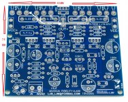
If you look at the original Musical Fidelity pcb that LJM posted you can see that PSU is only an inch or two away from the output transistors. With PSU so close one may not need bypass caps for absolutely stable performance. But LJM made clone board without PSU and many constructors will place PSU at greater distance from the amp board so it would be highly desirable to have bypass caps onboard near output transistors. It would probably be the easiest to place footprint for 100nF/100V SMD polyester caps on the bottom side of pcb near output transistors, if LJM decide to make some new version of the pcb.
One certainly does need local decoupling at a distance of an inch or so.................. PSU is only an inch or two away from the output transistors. With PSU so close one may not need bypass caps for absolutely stable performance.................
That inch or so implies a minimum flow and return circuit length of >50.8mm
That is enormous.
- Home
- Amplifiers
- Solid State
- I tried the eBay MX50 DIY Kit, Class AB 100W+100W; Worked but problem