Hum pot
Ralph,
Cheers,
Ralph,
For testing, I suggest you forget about the heater transformer centre tap. Just use the wiper of the hum pot to ground. If you can make the hum bearable with that, we'll try to think up something more clever.I have a spare 100 ohm/4W pot that I could use, but haven't figured out how to do it correctly.
Cheers,
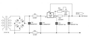
Some followup question, I try to use DC for the filaments, see picture. The voltage before the LM350 is 17Vdc. So it's a power disapation of 17-5=12Vx2A=24Watt. After 10 secs or so the LM350 shuts down, and feels extermely hot. Can it handle this amount of power?
Attachments
Hotting up..
Ralph,
I don't know that there is a defined max for the power that can be dissapated, except that the junction of the device will rise by 1.5 degrees for each watt with an infinite heatsink . So, any practical heatsink wiil have to be quite large.
What size heatsink do you have?
Do you know the thermal resistance (in degC/w)?
You will need a heatsink. The bigger, the better.
But, you should also try to minimise dissapation. This can be done by adjusting the values of the resistors in your smoothing circuit.
An interesing plus-factor, is that the greater you make their value, the smoother the DC will become, and so the regulator will be less affected by the troughs in the ripple.
I suggest you re-calculate the resistor values to get 4 volts across the regulator; that'll be 8 watts dissapation, which is more manageable.
Do you know how to calculate it? If you look back through the thread, I think there are sufficient clues.😉
Cheers,
http://www.national.com/pf/LM/LM350.html
John,
Ralph
Thought of that, but that means that I have to loose 8 Volts over the resistors (from 17 down to 9). At 2 amps, this is 4 Ohm/16 Watt. Need some pretty heavy ones for that.I suggest you re-calculate the resistor values to get 4 volts across the regulator; that'll be 8 watts dissapation, which is more manageable.
It's 4.8C/w. Is that good? I have to confess however that during my initial test I didn't use it because I was a little afraid of shortcircuiting the regulator due to the fact that the heatsink is made of metal. I was afraid the two pins might contact the heatsink and therefor the case of the LM350.Do you know the thermal resistance (in degC/w)?
Ralph
Something to think about...
Ralph,
It's better to dissapate the power in resistors than a semiconductor, from a reliability point of view.
There are 2 kinds of power resistor:
1) The kind that rise to a high temperature in free-air, and depend on convection to loose the heat - they can run very hot; sometimes hot enough to melt "low melting point" solder.
2) The kind that bolt onto a heatsink (or chassis), and lose heat through conduction.
Both have merits.
Heatsinks:
The regulator must have a heatsink. With the heatsink you describe, the heat rise will be 1.5 + 4.8 degrees C for each watt.
That assumes a clear airflow through the heatsink.
To my mind, that is barely adequate for the job.
I prefer to run semiconductors below 70deg.
Don't forget, we're talking about temperature rise here. So you have to conider the ambient temperature where the heatsink will live. Under-chassis, it might be 40 deg.
Cheers,
Ralph you might want to look at this solution.
http://www.dddac.de/at05.htm
doede douma
John, thanks for a very interesting thread. I learned a lot.
Frank, de groeten
http://www.dddac.de/at05.htm
doede douma
John, thanks for a very interesting thread. I learned a lot.
Frank, de groeten
Hi John,
Very interesting what you wrote about the heatsinks. Made me check my other regulator, the lm317 for the driver heater. It got very (too) hot, so I installed it on a better heatsink. Now I've calculated the new resistors to order.
- The 5687 heater measures 22.4 Vdc before the first C. I want to drop 22.4 - 12.6 - 5 (room to operate) = 4.8V. At 0.45mA this is approx 10 Ohm. So I need to change the resistors between the first and second cap to 10 Ohm/9 Watt, correct?
- At the 300B filament supply I want to drop 8 Volts, so I need 3R9 resistors/50Watt.
What a project
🙂
HOLD ON...
Hi,
Once your heatsink is appropriate for dissipating the heat due to the current drawn by the filaments,dropping the input voltage is not going to change anything.
The heat is not caused by the higher input voltage,moreover a regulator works optimal with at least 5V difference across it,going a bit higher will improve the regulation, going to low will prevent it from regulating at all.
Have I missed something?
Cheers,😉
Hi Frank,
I'm afraid that I can't find/accomodate a heatsink big enough for the filament current. I now have a small one 4.5x4.5x3 cm (4.6 c/W) that is just right enough for my driver heater (that LM317 only dissipats 4 Watts). For the 300B currect I would need such a big heatsink I can't place inside my enclosure I guess. Best I can find is a SK88 (0.8 c/W) or SK98 (0.74 c/W) but those are 15 cm!
I'm afraid that I can't find/accomodate a heatsink big enough for the filament current. I now have a small one 4.5x4.5x3 cm (4.6 c/W) that is just right enough for my driver heater (that LM317 only dissipats 4 Watts). For the 300B currect I would need such a big heatsink I can't place inside my enclosure I guess. Best I can find is a SK88 (0.8 c/W) or SK98 (0.74 c/W) but those are 15 cm!
300B
Hi,
Each 300B will consume 6W of heater power : 1.2A * 5V.
How many are you feeding from a single LM317 and what is the amperage rating of the 317 you using?
Several rating exist,so be careful not to exceed max. dissipation.
Cheers,😉
Hi,
Each 300B will consume 6W of heater power : 1.2A * 5V.
How many are you feeding from a single LM317 and what is the amperage rating of the 317 you using?
Several rating exist,so be careful not to exceed max. dissipation.
Cheers,😉
Frank,
My 300B's use 5V @ 2A. But the voltage drop over de LM350 (1 per channel, 3A max) is 12V. 12V x 2A = 24W dissipation.
My 300B's use 5V @ 2A. But the voltage drop over de LM350 (1 per channel, 3A max) is 12V. 12V x 2A = 24W dissipation.
NO,NO.
Hi,
It is a LM350 now?🙄
Nevermind.
Ralph,that does not matter.The current is still the same: 5V at 2A is 10W.
Whatever voltage you have in front of the reg doesn't change the power dissipated in the reg.
Cheers,😉
Hi,
It is a LM350 now?🙄
Nevermind.
Ralph,that does not matter.The current is still the same: 5V at 2A is 10W.
Whatever voltage you have in front of the reg doesn't change the power dissipated in the reg.
Cheers,😉
Hi Frank,
I use a LM317 (TO-220) for my drivertube and 2x LM350 (TO-3) for the 300B's.
I use a LM317 (TO-220) for my drivertube and 2x LM350 (TO-3) for the 300B's.
Please reread post #123, I'm sure either of you is mistaken here. And I'm fairly sure that all the voltage a regulator drops is transformed into heat.Whatever voltage you have in front of the reg doesn't change the power dissipated in the reg.
Ralph said:And I'm fairly sure that all the voltage a regulator drops is transformed into heat.
Well, it has to go someplace... I'm curious too, because my L7805CT gets fairly hot after a half hour or so.
Re: NO,NO.
Okay, here goes my first post in a Tubes thread. I've been following this thread with interest, though I know nothing about tubes (yet). But this I can comment on...
These are "linear" regulators, not switching types, and hence not very efficient. Ralph is correct that the dissipation is the voltage drop across the reg times the current drawn by the load.
fdegrove said:
Ralph,that does not matter.The current is still the same: 5V at 2A is 10W.
Whatever voltage you have in front of the reg doesn't change the power dissipated in the reg.
Okay, here goes my first post in a Tubes thread. I've been following this thread with interest, though I know nothing about tubes (yet). But this I can comment on...
These are "linear" regulators, not switching types, and hence not very efficient. Ralph is correct that the dissipation is the voltage drop across the reg times the current drawn by the load.
Hi Sparhawk,
Cheers, Ralph
. Well as you clearly could have read I also know little of tubes (just the basics) but I enjoy building my first amplifier very much and I really appreciate all the good help I get on this forum.though I know nothing about tubes (yet).
Cheers, Ralph
AH,...
Hi,
I see now...you want to regulate two different stages.
From different secondaries I suppose, so you can forget all I said before.
Your calculations seem correct and indeed you will need to dissipate the heater power + the minimum voltage drop (say 5 volts) through the reg.
The overvoltage in front of the reg can be burned off using a resistor unless you have a better use for it.
Sorry about the confusion Ralph,😉
Hi All,
I've been away for a while, and left some confusion, I think.
What I was telling Ralph, was to minimise the dissapation of the regulator.
Of course it needs a voltage drop to work properly.
It's true that 5 volts is a good drop to have across such a regulator, but that takes into consideration the ripple of it's input signal.
If Ralph were to "loose" some voltage across his smoothing resistors, there would be less ripple on the regulator's input.
Therefore I was suggesting that he might break "the 5v rule" by a volt.
Cheers,
- Status
- Not open for further replies.
- Home
- Amplifiers
- Tubes / Valves
- I really would like your help on my 300B project