I've been playing around with DC on my 300B's and most of the hum disappeared. The only thing is the enormous amount of heat coming from the LM350 (as you know). It's mounted on the largest heatsink I could find (0,7C/W) but still gets too hot after 1 hour.
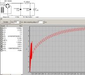
I've simulated the circuit to check if I could reduce the voltage a little bit but got strange results. PSU Designer says I have only 5 Volts or so before the regulator. What's wrong with this simulation? As you can see I use diodes (Schottky) - 6800uF - 0,12R - 2x6800uF.
Ralph
I've simulated the circuit to check if I could reduce the voltage a little bit but got strange results. PSU Designer says I have only 5 Volts or so before the regulator. What's wrong with this simulation? As you can see I use diodes (Schottky) - 6800uF - 0,12R - 2x6800uF.
Ralph
Attachments
Hi Ralph,
I'm glad your hum is better🙂
The simulator problem would appear to be the resistive value you've got for the caps.
2 Ohms is the default value in the sim. That is reasonable for a high voltage cap. For low voltage caps, such as yours, I would try a value of 100milOhms (0.1 ohm) to start with.
The resistive value of these big caps is always given by the manufacturer, and can be found in component catalogues such as RS and Farnell.
Another point may be to let the sim run on a little longer. But the resistance is the main thing.
Once you know the real input voltage, you can then start trimming it down, as suggested originally, to make your regulator manageable.
Cheers,
Hi John,
Thanks for that! Found some good datasheets on that cap: ESR (100 hz) = 0.059 ohm, 10K = 0.045 ohm, 100K = 0.064 ohm.
Now I can start experimenting with some caps. I just tried 3.9 Ohm and it worked OK, VinLm350 drops to 12.2V. Am I correct that only the "Plus"-resistor between 1st and 2nd cap needs to be high wattage (now 50Watt). The "Neg"-resistor can be 3.9 Ohm/1 Watt or so?
Cheers, Ralph
Hi Ralph,
Since they pass the same current, the resistors need to have the same ratings!
Cheers,
Since they pass the same current, the resistors need to have the same ratings!
Cheers,
Running them for 30 mins now, the "Plus" resistor is extermely hot, the "Neg" one is cold as ice ...
Edit: after 45mins the Neg one is getting a little bit warmish..
Edit: after 45mins the Neg one is getting a little bit warmish..
Ralph,
Are the 2 resistors the same value? My comment was based on that understanding.
If they are, please compare the voltage across each one.
If there is no, or little, voltage across the bottom one, I suggest one of the following is true:
1) You've made an error in reading it's value.
or,
2) You have earthed both sides of it.
Only the valve side should be earthed.
This can happen easily in mounting the capcitors, as the negative terminal is often internally connected to the case.
Cheers,
John,
Looks like I made a mistake (again). I did connect both sides of the lowerresistor to earth. That means, the first cap is also eathed. I'll remove that first cap-to-ground-connection. Hope I didn't damage things by connecting it incorrect ...
Thanks again 🙂
Looks like I made a mistake (again). I did connect both sides of the lowerresistor to earth. That means, the first cap is also eathed. I'll remove that first cap-to-ground-connection. Hope I didn't damage things by connecting it incorrect ...
Thanks again 🙂
Hi Ralph,
Hopefully the regulator will cool a bit now.🙂
I don't think any damage has been done.
Cheers,
Hopefully the regulator will cool a bit now.🙂
I don't think any damage has been done.
Cheers,
Hi John,
Now I measure 11.0Vdc at the regulator. Over the upper resistor I measure 5.95Vdc (and 3.0Vac) over the lower 0.0Vdc / 3.0Vac. The lower resistor is now also getting hot (although not as hot as the upper one)
Cheers, Ralph
Now I measure 11.0Vdc at the regulator. Over the upper resistor I measure 5.95Vdc (and 3.0Vac) over the lower 0.0Vdc / 3.0Vac. The lower resistor is now also getting hot (although not as hot as the upper one)
Cheers, Ralph
Ralph,
How are you measuring this?
The most meaningful way, is to connect the meter probes directly across the resistor, and read the voltage directly.
According to your schematic, the resistors are effectively in series, so, if they are the same value, the voltages must be identical.
If they are more than ~10% different, there is a mistake somewhere.
Cheers,
John,
I measure it exactly as you described, just over the R itself. Take a look please:
http://www.homepages.hetnet.nl/~rjonkers/circuit.jpg
Cheers, Ralph
I measure it exactly as you described, just over the R itself. Take a look please:
http://www.homepages.hetnet.nl/~rjonkers/circuit.jpg
Cheers, Ralph
Thanks John, works as expected now 
Dropping 5V over the regulator @ 1.6A = 8 Watt. With my 0.7C/w heatsink this will be 40C (inside box) + 8x(0.7+1.5) = 57.6C. Nice and cool ...
Ralph
Dropping 5V over the regulator @ 1.6A = 8 Watt. With my 0.7C/w heatsink this will be 40C (inside box) + 8x(0.7+1.5) = 57.6C. Nice and cool ...
Ralph
Hi Ralph,
I knew you'd get there!
By the way:
Looks very nice indeed.😉
Cheers,
I knew you'd get there!
By the way:
Meanwhile, I'm also finishing my enclosures, one for the PSU and one for the amp. Nice, aren't they
Looks very nice indeed.😉
Cheers,
Hi John,
Just another (more general) question, hope you don't mind. As you can see from the picture of the circuit on my workbench, that's not the most practical way to build in into a enclosure with all those wires etc. Let's take the filament supply as example.
Parts include (for one channel):
- 4 schottky diodes
- 1 heavy heatsink (15x8x4 cm)
- some resistors (incl 2 heavy resistors 50W)
- some caps (3 electrolyts + 2 tantal)
Right now everything is hold together with tape and wire. But what's the best way to 'organize' this circuit for building in? Do I for example need some kind of PCB?
Another question re the diodes. As you can see I now use some 50V 5A Schottky diodes, but like to try the ones you've suggested (TO-220). They need to have a small heatsink I guess but I also see problems in connecting them together properly and don't have wires lying around everyting. Ideally there was some kind of (small) heatsink where I could mount all 4 TO-220 diodes onto and in the same time connect them together properly. Then we have the advantages of a standard bridgerectifier (small, compact, already connected) and still have the advantages of the Schottky TO-220 diodes.
Is there a general rule if diodes need to have a heatsink though? the ones in my V- circuit also have so no heatsink nor the ones in my 5687 heater circuit. If one uses ordinairy diodes, it seems to me that it's hard to mount them, isn't it?
A lot of questions once again 🙂
Cheers, Ralph
Hi Ralph,
There are lots of ways to do it. Here's how I would tackle it:
A PCB is unnecessary for this design, unless you wanted to mass produce it. Point-to-point wiring has many advantages.
Deciding whether to heatsink a diode, only depends on how hot it is getting in the application. If you can hold your finger on the diode for 5 seconds, I would say it is OK as it is. They will lose heat by convection, and conduction through the thick leads.
If you mount them between stand-off insulators, I advise to leave at least 10mm of lead on each side.
The TO220 diodes are just more convenient in all respects. If you go for this package, chose the type with a plastic coated tab, then you won't have to mess with insulation washers and bushes.
The regulator: I would find a smaller heatsink that has a flat side. Then mount the heatsink onto the chassis underside using thermally conductive grease.
Don't forget, you'll need to fit a TO3 insulation kit to the regulator before mounting the heatsink.
The resistors can be mounted on the chassis, or on a bracket, on the inside of the plinth. These can be allowed to get very hot: over 100degC, so keep the wiring clear, and use PTFE insulated wire for their connection. Or you can sleeve the connection wires with PTFE sleeving, near the resistors. (Remove 10mm of the PVC insulation in this case).
Others will have different ways...these are mine.
Cheers,
Hi Ralph,
I forgot some things:
Caps:
There are mounting clops available, but these are mainly for radial types. The axial type you are using can be mounted with large "P" clips, or you can make your own bracket and use "tywraps". The smaller caps can generally hang on the more ridgid components.
Layout:
This is the biggest subject. It'll be up to you to ask the specific questions that bother you. Check the forum, especially about transformer orientation.
On your prototype, put the transformers in the positions you wish, and check for hum.
Earthing:
Is most important, both for safety, and performance.
This has been covered. Check the forum.
Cheers,
Thanks John,
As you can see from my testcircuit, there are 2 pins going through the heatsink (adjust and Vin) and one solderpin connected to the mounting screws of the LM350/case (Vout). So it seems impossible to skew the heatsink to the chassis, isn't it?
Ralph
The regulator: I would find a smaller heatsink that has a flat side. Then mount the heatsink onto the chassis underside using thermally conductive grease.
Don't forget, you'll need to fit a TO3 insulation kit to the regulator before mounting the heatsink.
As you can see from my testcircuit, there are 2 pins going through the heatsink (adjust and Vin) and one solderpin connected to the mounting screws of the LM350/case (Vout). So it seems impossible to skew the heatsink to the chassis, isn't it?
Ralph
Ralph,
Yes, I think it is not possible with that design of heatsink. It's also rather large for chassis mounting. But there are profiles that are smaller, and it's possible.
Cheers,
Yes, I think it is not possible with that design of heatsink. It's also rather large for chassis mounting. But there are profiles that are smaller, and it's possible.
Cheers,
Hi John,
How do I connect them together? I mean, do I just use wire to connect the tiny legs together of the 4 diodes (STPS745F)? Looks like a mess. More so when I want to also connect 4 small 100nF caps over the diodes. A normal BR is much easier, not?
Cheers, Ralph
The TO220 diodes are just more convenient in all respects. If you go for this package, chose the type with a plastic coated tab, then you won't have to mess with insulation washers and bushes.
How do I connect them together? I mean, do I just use wire to connect the tiny legs together of the 4 diodes (STPS745F)? Looks like a mess. More so when I want to also connect 4 small 100nF caps over the diodes. A normal BR is much easier, not?
Cheers, Ralph
- Status
- Not open for further replies.
- Home
- Amplifiers
- Tubes / Valves
- I really would like your help on my 300B project