A question that has nothing to do with the subject.
If, for example, I cut the bass at 400hz or bandpass from 500hz to 3khz, what happens to the 100hz that are between 400 and 500hz? Are these frequencies lost?
If, for example, I cut the bass at 400hz or bandpass from 500hz to 3khz, what happens to the 100hz that are between 400 and 500hz? Are these frequencies lost?
Yes, what you are looking for does not appear to be out there, at least in simple terms.
The mathematics is obviously difficult and that's why people use a computer program to do the calculations.
I can only offer this calculator (shock horror!) for you to play with: https://www.claredot.net/en/sec-Sound/band-pass-cross-over-6dB.php
I'm going to take the weekend just to read about this and these calculators
I'm going to buy a precision microphone just to use these apps...It is - just like everything you start to dig into!
Once you know just a little more it's getting even more mysterious.
But once you start using simulation tools it will get much more intuitive!
Soon I'll be asking about them
Are these frequencies lost?
They would not be completely lost. Since the crossover slopes are shallow they will overlap and sum to fill the narrow gap in frequencies.
So there is no problem if I make a filter for the bass at 400hz and start the midrange at 404hz?
I thought it would cut the frequencies that were in the middle, or at least leave them lower.
In the music itself, wouldn't that make a difference? it wouldn't harm the sound so to speak
I thought it would cut the frequencies that were in the middle, or at least leave them lower.
In the music itself, wouldn't that make a difference? it wouldn't harm the sound so to speak
So there is no problem if I make a filter for the bass at 400hz and start the midrange at 404hz?
Why wouldn't you just calculate for 400 Hz? You are making a problem where none requires to exist!
Here's how a 1st order, 3-way Butterworth filter is designed to cross:
The crossover slopes (full lines) are made to overlap so that the responses at fL and fH are 3 dB down.
This ensures that the overall response (horizontal dotted line) sums to flat.
Last edited:
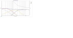
For illustration, I've attached a Xsim simulation of a three way speaker using well behaved and inexpensive drivers from Peerless: a 6.5' woofer, 5" mid and 1" dome tweeter.
It's only a simulation, based on graphs supplied by the manufacturer, but I've uploaded it to show you an example of the different values of the parts needed to get a reasonable response.
A real world, measured in box simulation will be different, but the principle's the same. The crossover points for this speaker are a bit high in the case of the woofer, and a bit low for the tweeter, but for this purpose that isn't too important, they can be moved up or down by using different value parts.
In the second graph, the blue line is the overall response, black the tweeter, orange the mid and red the woofer. You can see how the top and bottom ends of the mid are rolled off, they don't just stop producing sound.
Attachments


A previous post of mine was aimed at studying how to find capacitors by calculations...
I researched and researched and did the math to find the capacitor for my midrange using the 1mH inductor, I also tried with 0.2mH but I found the found value of the capacitor a bit difficult to find...
Set the cutoff frequency to 8 times that of Low-pass (400hz to 3000hz).
In reality it would be 3200hz but I didn't find any problems in rounding it to 3000hz.
The value of the average capacitor would be 21.14uf. I'm seriously thinking about getting a 22uf or 21uf capacitor, any ideas?
Did I do something wrong or is there something I can improve?
Both L (inductance) and C (capacitance) are related to load impedance. You need to search for a filter design of the high or low pass. The number of elements (L's and C's) depends on the slope of the filter and their values upon rhe kind of filter (Tchevishev, Butterworth, Bessel, etc.). Each one has its own pros and cons and it's your decision to choice one. There are online filter calculators too.
Don't buy any components yet. It will be a disappointment.getting a 22uf or 21uf capacitor
You really need to get a simulation tool and use real impedance curves and the planned enclosure.
A complete package would be vituixcad or (much simpler and less powerful) boxsim. Both free for private users.
Edit: the problem with your calculation is that you assume 4 ohms for all speakers at all frequencies. That is far from reality. 4 ohm is just the nominal value.
Therefore your calculated values will be far off.
Also you need to consider the influence of driver frequency responses and the baffle.
Edit2: also, you should continue in one project thread. Otherwise it's very difficult to keep track of all the information.
You can ask moderators to join threads.
Last edited:
I can even download the applications but the problem is that I'm still very new in this area...
Everything I've learned so far was here practically talking to the veterans.
I don't even have the microphone yet to simulate
Everything I've learned so far was here practically talking to the veterans.
I don't even have the microphone yet to simulate
Just click the "report" button and ask a moderator to join the threads!
if you ask kindly someone (I?) might even start a simulation and send the file to you for further tweaking!
(Edit) read through this tread:
https://www.diyaudio.com/community/...igning-crossovers-without-measurement.189847/
if you ask kindly someone (I?) might even start a simulation and send the file to you for further tweaking!
(Edit) read through this tread:
https://www.diyaudio.com/community/...igning-crossovers-without-measurement.189847/
Both threads are merged now. I removed a double post and a few obsolete ones.
Hugo
Hugo
Should I buy the components or not?
I suggest you do not as your component values do not match what a simple calculator would indicate using 4 ohm drivers with fL = 400 Hz and fH = 3200 Hz (3000 Hz can not be inputted).
@Pedroga
Please allow me to tutor you on the correct use of the unit abbreviations commonly used in crossover calculations.
Note, in particular, which letter in the abbreviation should be capitalised.
Please allow me to tutor you on the correct use of the unit abbreviations commonly used in crossover calculations.
Note, in particular, which letter in the abbreviation should be capitalised.
- Frequency: hertz (Hz or kHz)
- Inductance: millihenry (mH)
- Capacitance: microfarad (μF or uF)
Last edited:
What do you need to do the simulations?
Links to the specifications of the exact woofer, midrange and tweeter drivers you intend to combine together.
- Home
- Loudspeakers
- Multi-Way
- I put together a simple 3-way crossover diagram and I have some doubts about it