Hi,
I started the amp up and recorded the voltages and changes are indicated on the attached schematic.
The channel connected to V1 pin 2 works normally and sounds good.
The channel connected to V1 pin 7 is producing very little gain. ( resolved tone control has to be turned up)
The tremolo circuit is not working. I used a 500K pot with a turn-on switch, and I am not sure if it is connected correctly ( the on-off part).
Also, can someone explain the 100-volt difference in the V1 plate voltages (pin 6 at 145vdc and pin 1
255vdc)?
The handwritten numbers are mine. The printed numbers are Steve Luckey's numbers using a different PT.
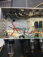
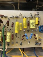
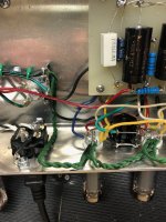
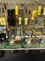
I have a series of high-rez photos of the amp if needed.
I have done several hours of troubleshooting without success.


Thanks,
Billy
I started the amp up and recorded the voltages and changes are indicated on the attached schematic.
The channel connected to V1 pin 2 works normally and sounds good.
The channel connected to V1 pin 7 is producing very little gain. ( resolved tone control has to be turned up)
The tremolo circuit is not working. I used a 500K pot with a turn-on switch, and I am not sure if it is connected correctly ( the on-off part).
Also, can someone explain the 100-volt difference in the V1 plate voltages (pin 6 at 145vdc and pin 1
255vdc)?
The handwritten numbers are mine. The printed numbers are Steve Luckey's numbers using a different PT.
I have a series of high-rez photos of the amp if needed.
I have done several hours of troubleshooting without success.
Thanks,
Billy
Last edited:
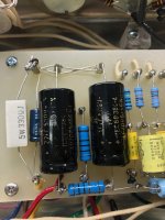
More photos
Attachments

Though the plate resistors (270K) and plate supply voltages (278 volts) are the same in both sections, the cathode bias resistors (2.2 k vs 1.5 k resistors) are different.
Lower negative bias (-1.0 V) means higher plate current and higher negative bias (-2.3 v) means less plate current.
So the voltage drop across the plate resistor is higher when the plate current is higher.
Negative bias is grid to cathode voltage, which is negative.
Regards.
Lower negative bias (-1.0 V) means higher plate current and higher negative bias (-2.3 v) means less plate current.
So the voltage drop across the plate resistor is higher when the plate current is higher.
Negative bias is grid to cathode voltage, which is negative.
Regards.
Thank you for the explanation. I have never been very knowledgeable about circuit analysis. Also, I stopped building amps about five years ago and have forgotten many things.
Some skills like flying airplanes have remained the same although my reaction time is not as quick. I am pushing eighty and getting older has its downsides.
I am really struggling with the tremolo not working issue but I will figure it out sooner or later.
Thanks again for the education!
Billy
Some skills like flying airplanes have remained the same although my reaction time is not as quick. I am pushing eighty and getting older has its downsides.
I am really struggling with the tremolo not working issue but I will figure it out sooner or later.
Thanks again for the education!
Billy
A phase shift oscillator requires a voltage gain of 29 (from memory) to start oscillation.
The 1.5 meg grid resistor provides bias for the tube when the tube oscillates.
Check the phase shift capacitors values are correct.
Jumper the cathode resistor and try as it might reduce the gain when it starts oscillating.
Regards.
The 1.5 meg grid resistor provides bias for the tube when the tube oscillates.
Check the phase shift capacitors values are correct.
Jumper the cathode resistor and try as it might reduce the gain when it starts oscillating.
Regards.
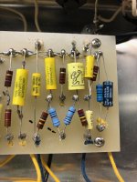
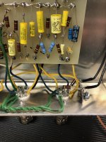
Thank you ever so much! Bad .047 cap.
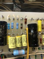
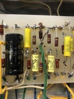
To add insult to injury, I had left a short jumper wire off. When I saw that, I thought I had solved the issue ( see T2.jpg, .0047 to .047 jumper not there in the photo). Tremolo still would not work. I started checking caps and found the issue based on what you said.
I am almost done with the electronics. I currently have the amp playing through a vintage 12" Celestion speaker. I was able to buy a used 15" Supro speaker which is delayed in the US mail.
The amp sounds very good to me the way it is. Very mid-1960s rock tones. Perhaps it will be better with the 15" speaker, we will see.
Thanks again,
Billy

- Home
- Live Sound
- Instruments and Amps
- I need some help solving Issues with my new Supro S-6424 build