Hey guys,
So I've made a few HIFI units for myself without a lot of issues and they sound great. My company does activity funds so my plan is to have them come to the shop (I run the manufacturing side of this electrical engineering consulting company) and build a little two way system.
The plan is to make 30 of these units. One unit for one employee and they can bring whoever they want to help them assemble it. Seems fun
I am limited to about $60 a person so I have this dayton 4" high excursion woofer and this mini tweeter plus a tiny amp pushing 20w. I'm trying to cross them around 4k hz. I've never done this with a budget so low and I'm having issues with the impendence graph as you can see below. Usually I have higher end components I can choose more carefully so the Xover doesn't need to be so severe. Its all over the place and I'm wondering how to fix this. I want to use this woofer specfically because I am able to get this thing down to 40 hz Fs using some unique methods I've learned building subwoofers. The tweeter I am not married too. I can swap that out with anything you suggest.
Does anyone have any suggestions of what I can do to get this to behave?
Mini Planar Tweeter 6 ohm:
https://www.parts-express.com/Dayton-Audio-PTMini-6-Planar-Tweeter-6-Ohm-275-083?quantity=1
4" Woofer 8 ohm:
https://www.parts-express.com/Dayto...-Cone-Midbass-Woofer-8-Ohm-295-416?quantity=1
I appreciate any help anyone can give me here. Would be a shame to make 30 of these and have them suck
Attachments
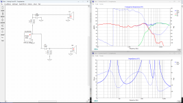
Not sure those impedance plots matter a lot. Minimum seems about 7 ohms, that's easy-peasy for the amp.
Your freq response looks nice, the xover does what it is supposed to do.
I once did a similar activity, SpeakerCamp, 28 pairs.
The prudent thing to do is build a prototype to fix all wrinkles before going all out.
And there will be wrinkles, no doubt about that.
You don't want to disappoint your coworkers!
Jan
I'm definitely building a prototype. I will be putting switches into it so I can run just the woofer, then just the tweeter, then woofer/tweeter, then woofer/tweeter/with crossover as a demonstration of what we are doing.

Have you measured or otherwise included your baffle step?
Could you post the Xsim savefile (*.dxo)
Could you post the Xsim savefile (*.dxo)
Hey Allen,
II have actually never included baffle step into my designs. I have a loose idea of what that is and have never had any issues with lower frequencies lacking. That's likely due to me always porting the low end so I basically always end up with a highly frequency response down low than up high. This is fine for me as I like that.
SWhen I'm back at work tomorrow I'll send you the xsim file, the WinIsd file/graph, and a screenshot of my cad design that has my dosnfiring port in it
These will end up with an Fs of about 37 hz. Lots of young people at my company so bass is all they're going to want.
II changed up the tweeter and redid it again. I was unhappy with what happened after 10k hz on that other one. Spent a few bucks more for a little better tweeter.
Assuming a small baffle about bookshelf size.
Then yes baffle step would be high to very high in frequency .
Then overall driver position/ phase relation to how they are mounted
on the baffle as well
Otherwise you sim is close to a coaxial on a AES test baffle.
Which wont be real world.
Inductor capacitor values will have big effect on those impedance peaks.
Also can be smoothed out or high Q can be fixed with impedance compensation.
Just need size of baffle.
could move from there.


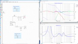
Ok, here's everything I have so far.
I swapped out the planar tweeter for this neo tweeter. I read some of the reviews and it seems that planar is really finicky to work with. Not a gamble I want to make on a 30 unit build. I also didn't like the way it behaved past 10k hz. Woofer Is the same. This forum is not allowing me add the WinISD file for some reason.
Woofer 4":
https://www.parts-express.com/Dayto...-Cone-Midbass-Woofer-8-Ohm-295-416?quantity=1
Tweeter:
https://www.parts-express.com/Dayton-Audio-ND25FA-4-1-Soft-Dome-Neodymium-Tweeter-275-059?quantity=1
I am budget limited on the crossovers so its just all 2nd order butterworth. Inductors drastically increase the cost of the entire thing. I can throw as many caps as I want at it though and it only cost $30 extra a cap basically. The crossover isn't great but again, budget limits make this about the most difficult build I've ever done. Throwing money at a project is just so much easier.
You'll see my baffle is quite large for the size of the driver. I want it to hit low. I can offset both the woofer and the tweeter to reduce edge diffraction issues. I just want to keep that port directly behind the woofer. I would like those rear frequencies to get split down the middle by the port.
Let me know what you think or if anything stands out to you as just plain wrong
Attachments
Were hoping for off axis performance of course.
But 2nd order filter is less cutoff. So for performance
you want to keep crossover high as possible for
distortion. Or the most part, to low frequency
on a tweet will usually get the surround buzzing.
But yes off axis were trying go lower.
Basically best chance at getting that to happen.
Is using the small form factor of that tweeter.
Get tight tight center to center spacing.
At high frequency just standard goal anyways.
Drivers are mounted very very close.
And these newer neo tweets are actually perfect
for that. Since sizes are rather small.
8" x 13" sounds good to me.
Surprised, good to see wider
so baffle step is somewhat easier.
Correct for flattest diffraction slightly offset.
No edge distance the same.
Tweeter/ listening position could be almost centered.
But flatter be up higher as well, and slightly offset. So shorter
distances are not equal
8x13" or 200 x 330mm
Best tweeter position that is realistic
for flat response is 120 x 280mm
Which used as listening position as well.


Same with woofer, for best possible diffraction.
And physically close to tweeter as possible 70 x 195mm


Attached is Full_Space FRD / ZMA files for that baffle
including all off axis.
phase is correct for listening position.
Should not have to position those files in sim
But 2nd order filter is less cutoff. So for performance
you want to keep crossover high as possible for
distortion. Or the most part, to low frequency
on a tweet will usually get the surround buzzing.
But yes off axis were trying go lower.
Basically best chance at getting that to happen.
Is using the small form factor of that tweeter.
Get tight tight center to center spacing.
At high frequency just standard goal anyways.
Drivers are mounted very very close.
And these newer neo tweets are actually perfect
for that. Since sizes are rather small.
8" x 13" sounds good to me.
Surprised, good to see wider
so baffle step is somewhat easier.
Correct for flattest diffraction slightly offset.
No edge distance the same.
Tweeter/ listening position could be almost centered.
But flatter be up higher as well, and slightly offset. So shorter
distances are not equal
8x13" or 200 x 330mm
Best tweeter position that is realistic
for flat response is 120 x 280mm
Which used as listening position as well.
Same with woofer, for best possible diffraction.
And physically close to tweeter as possible 70 x 195mm
Attached is Full_Space FRD / ZMA files for that baffle
including all off axis.
phase is correct for listening position.
Should not have to position those files in sim
Attachments
Extra cap on tweet makes 3rd order helps
Only 2 coils
flat response and impedance .......zing


Only 2 coils
flat response and impedance .......zing
Thanks for all the help!
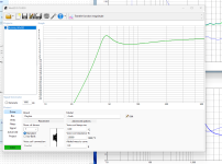
I see now what the edge defraction does to the frequency response. How did you make those files? What software?
And thank for fixing up that crossover. That really smoothed everything out. You're clearly more experienced than I am.
I see now what the edge defraction does to the frequency response. How did you make those files? What software?
And thank for fixing up that crossover. That really smoothed everything out. You're clearly more experienced than I am.
Virtuix CadHow did you make those files? What software?
pretty much does everything diffraction , crossover , enclosure
trace tool to get frd from datasheets if needed.
little learning curve.
But you could also load the full FRD files from that
file and sim baffle shown.
For the price that Dayton tweet actually does very well in
real life as well. Surround holds up at high levels
I like 3rd order to ensure it little better.
Just playing around with the diffraction tool.
Will really answer a lot of questions or unlock many mystery
of speaker design. And the results make more sense seeing the
visual. It is just a fun program to learn and design from.

Think your intentions were pretty good with the reflex.
Just from typical driver experience.
Looks like you were keeping tuning low. Good idea
and were keeping box large. usually good idea.
Cutoff stating to dip like that in blue is actually OK
lots of people try to high tune to flatten it.
When real butterworth will usually look the same
in speaker land.
A electrical filter having such high Q in the red
would not be all that pretty. Little much resonance.
Speaker land it usually tells me tuning frequency is
kept low, good idea. But its losing control of speaker
compliance. Might smooth that out reducing volume of enclosure
At least a guess, cant see volume or tuning in screenshot.
unless intentional to get more oooph
In real world its hard to get 2 or 3 dB of boost from a port.
Better to have smooth controlled cutoff in transfer function.
Real bass that works, is the actual 3 to 5 dB you add back
with everyday EQ or bass knob.
The box and port should just show good control of the speaker
suspension. Basically set tuning 3 Hz above or below Fs of the speaker.
Adjust volume to make suspension compliance happy n smooth all the way across
the transfer function.

I can get pretty close to your transfer function
showing control loss and resulting peak.
About 6 liters of volume. in blue
For reference I find largest Box size
for .577 Qtc in sealed box.
In yellow you can see 3.5 liters
is about the largest box you want to maintain
good control over the suspension.
Switching back over to green ported.
As you see reducing volume gained control
over that peak. Now its smooth and still
controlled even tuned low. Low tuning
or tuning at Fs usually works good.
Then adjust volume to make speaker compliance
happy
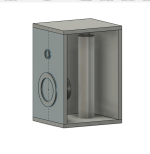
Originally I had a curve exactly what you show there. Pics below of my original intention. The issue I ran into is port length. I couldn't keep chuffing under control without a really long port. I can easily design in CAD a port that twists and turns into the enclosure to get the length I need, however, I couldn't figure an orientation to print that sort of twisted port on my printer. I scrapped it and went with a bigger box so I could use a shorter port. Iron's Law was not behaving for me.
Attachments
To answer a couple of your other questions here:
This was tuned at max volume running the full 20W the little amp is capable of. I wanted to design this around max volume so everyone could crank it to max volume and not run into the whole sound falling apart when they show it off to their friends.
I could have more control over the sub if I kept the wattage at 5 or even 10 and then run a smaller box. But again, these are designed for non audiophiles like you and myself. That doesn't mean I want to do a bad job, just that I want to factor in my audience's preferences. I've been to a lot of venues where the bass is horrendously muddy but it hits LOW. I have overheard people talking about it saying how its the best bass they've ever heard.
Is there a way around port length inside such a small enclosure other than flaring both ends and hoping for the best?
I've found what's most important to the less trained ear on a build like this is getting low, not so much SQ down there. Even for me, I'll take muddy bass over no bass all day. With the newer music you're really music a large part of the sound if you can get below 70 Hz. My listening unit at home hits down to 19 Hz. With that tower you might as well be listening to entirely different songs since they sound so differently. I threw quite a lot of money and engineering time into that one though. Worth every penny.
Sometimes a speaker is what it is.
I applied power with tuning to 45 Hz to 55 Hz
To see the unloading.
Most people would tune high. I like your approach
keeping it low for cone control.
I apply power and look at cone excursion.
I look at resonant frequency in box which is around 80 Hz
in 3 to 5 liters. Divide in half
Even though it doesn't do 40 Hz very well. The speaker
will at least try do so.
So im looking at unloading at 40 Hz and looks like 15 to 20 watts
is Xmax or 10% distortion. So realistic power be 7 to 10 watts.
Velocity can be 18 to 22 m/s
So you can use pretty small port. Its not like a sub
where vent energy is issue.
Otherwise you notice end correction factor in WinIsd is
standard .732 to .850
Why slot ports are common for small boxes.
The efficiency is rather poor, but works out
because lengths are much much shorter, when a
port shares 3 walls. Appears longer , end correction factor goes
above the decimal point 2.227
So I use VirtuixCad to design slot ports. Only because
Winisd end correction is .850 max.
In other sims you can raise end correction to 2.227
Slot ports will cause the boxes to be much more difficult to build. I want to keep this as simple as possible for the employees. Hot glueing in a flared port is super easy for them.
The less they use the bradley nailer the better. The last thing I need is someone shooting a nail into their finger.
Should I be basing the signal strength in WinIsd off of10 watts? I know that's what the speaker actually sees with after the crossover and the split.
I always thought you based it on the total wattage of the system. I guess I was wrong.
If I can base it off of 10 watts then I can make the port much shorter and smaller.
If your amp can produce 12.65 volts (20 watts at 8 ohms) you should expect users to use all it has, which could be directed to the woofer or tweeter/resistor or any combination.Should I be basing the signal strength in WinIsd off of10 watts?
Amp clipping will increase the average power the speaker sees..
That said, if impedance is 15 ohms at Fb, the driver only sees 10.5 watts at that frequency, so you could base port velocity on that .
Your enclosure depictions show the port exiting the cabinet bottom, so the port would be covered if sitting on any flat surface in the vertical orientation shown.I just want to keep that port directly behind the woofer. I would like those rear frequencies to get split down the middle by the port.
Let me know what you think or if anything stands out to you as just plain wrong.
Feet could be used, and could reduce the port length for a given Fb, but adds cost.
The port could exit on top, but probably want to screen it to keep it from becoming a trash receptacle 😉.
- Home
- Loudspeakers
- Multi-Way
- I need help with the impendence of this Xover