I have not build it yet.
I don't have money to make it.
I make gain clone lm386, it sound very good.
thank you for suggestion.
maybe someday I try to build it for fun.
I don't have money to make it.
I make gain clone lm386, it sound very good.
thank you for suggestion.
maybe someday I try to build it for fun.
jacco vermeulen said:Sorry about the delay.
I have 40 years of audio history articles, i could open up a museum if i knew how to archive.
jacco vermeulen said:Here is the AXL.
This one i built, using the 135/50.
Intended for 60% class A at 30V or in AB at 45V.
I added two Mosfets, with 1.8A bias at 30V it did 25 watts class A both in 8 and in 4 Ohm like the ML2.
Before building it in a chassis i had it on a wooden panel with dual powersupplies.
Switching from one channel in class A to the second in AB with a relay enabled me to compare.
First time i noticed Mosfets sound cold and hard in AB, warm and soft in class A, by the end of the 80s opamp/mosfet designs made this even more apparent.
Hi, can you post this two project more bigger???
thanks
A.
troubleshooting of AXL amplifier
I have rebuilt my AXL. I'm using 2SK135/2SJ50 now. Both are supplied with independent power supply, i.e. one channel one power supply. Both power supply work just fine. I use 2 22000mfd/50V electrolytic capacitor from panasonic japan for each power supply. Output voltages are 30Vdc. However, I experienced extreme and increased heat on the 2SJ50 (it cannot be touched! Well, it can actually, but it burned my forefinger) at one of the channel. The other channel is work just fine. I have tried to change all of the BC550/BC560 and BF469/BF470 for the trouble channel. The problem is remain unsolved. Should I replace all of the 4148 and 12 & 15 V zenner diodes? Any suggestion please....thanks in advance
I have rebuilt my AXL. I'm using 2SK135/2SJ50 now. Both are supplied with independent power supply, i.e. one channel one power supply. Both power supply work just fine. I use 2 22000mfd/50V electrolytic capacitor from panasonic japan for each power supply. Output voltages are 30Vdc. However, I experienced extreme and increased heat on the 2SJ50 (it cannot be touched! Well, it can actually, but it burned my forefinger) at one of the channel. The other channel is work just fine. I have tried to change all of the BC550/BC560 and BF469/BF470 for the trouble channel. The problem is remain unsolved. Should I replace all of the 4148 and 12 & 15 V zenner diodes? Any suggestion please....thanks in advance
Better solution..
Stuck with a pile of darlingtons ...
and reeling from destroyer's comment that a high fidelity
darlington output amp could not be constructed, I found
multiple solutions.
1. This amp with no compensation to counter switching
distortion:
2. the Elecktor amp (earlier in thread)which uses a bypass cap like DX suggested.
3: The modern and true fidelity,cheap solution is:
This amp with proper layout, better drivers,
Mn2488/mp1628 (sanken) X 2 for 4 ohms will give
a full stereo amplifier at-
100W 8R0 / 200W 4R0 , all for 25$ (LM4702a-7+$+ trannies/16+$)
The amplifier driven with the LM4702 gives VERY low
IM + THD (.001%)but with the "balls" of a discreet topology.
"Gainclone with teeth" is a good way to describe it, and
I'm sure it will sound as good if not better than most DIY.
Plans are here:
http://ts1/pdf1/Electronics/Projects/Audio_amp/Hybrid_darlington/
I will create a thread as soon as the chips arrive..
OS.
Stuck with a pile of darlingtons ...
An externally hosted image should be here but it was not working when we last tested it.
and reeling from destroyer's comment that a high fidelity
darlington output amp could not be constructed, I found
multiple solutions.
1. This amp with no compensation to counter switching
distortion:
An externally hosted image should be here but it was not working when we last tested it.
2. the Elecktor amp (earlier in thread)which uses a bypass cap like DX suggested.
3: The modern and true fidelity,cheap solution is:
An externally hosted image should be here but it was not working when we last tested it.
This amp with proper layout, better drivers,
Mn2488/mp1628 (sanken) X 2 for 4 ohms will give
a full stereo amplifier at-
100W 8R0 / 200W 4R0 , all for 25$ (LM4702a-7+$+ trannies/16+$)
The amplifier driven with the LM4702 gives VERY low
IM + THD (.001%)but with the "balls" of a discreet topology.
"Gainclone with teeth" is a good way to describe it, and
I'm sure it will sound as good if not better than most DIY.
Plans are here:
http://ts1/pdf1/Electronics/Projects/Audio_amp/Hybrid_darlington/
I will create a thread as soon as the chips arrive..
OS.
Re: troubleshooting of AXL amplifier
Build up a mains light bulb tester.
Connect the amp to the light bulb tester's outlet socket.
I suspect that the light bulb will light. If the amp were working properly it should flash and then gradually dim to a glow.
Now measure the voltage on the speaker output and on the supply rails.
Now switch off.
Compare the good channel voltages to the bad channel voltages.
Are they different? Report back.
and post a schematic.
Do not power up any modified or new project straight from the mains. Always use a light bulb tester for first power up.ynotthea said:I have rebuilt my AXL. ....................... I experienced extreme and increased heat on the 2SJ50............. Any suggestion please
Build up a mains light bulb tester.
Connect the amp to the light bulb tester's outlet socket.
I suspect that the light bulb will light. If the amp were working properly it should flash and then gradually dim to a glow.
Now measure the voltage on the speaker output and on the supply rails.
Now switch off.
Compare the good channel voltages to the bad channel voltages.
Are they different? Report back.
and post a schematic.
AXL problem
Dear Andrew
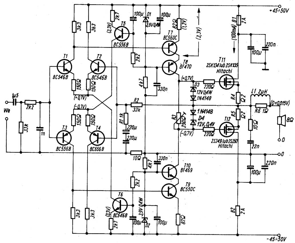
Thank you for your prompt respond. Anyway, I haven't had a chance to try your recommendation. The schematic for axl is as already posted by Meneer Jacco Vermeulen on 12-20-2004 (see post #52). One thing I observe is extreme 2 A bias current to the 0.22ohm resistor (R28) toward the SJ50 mosfet, while almost 0 A bias current to the other 0.22 ohm resistor (R27) toward the SK135 mosfet. Fyi, the P1 is set to maximum resistance value (1k). This happen only for one channel (right), while the other channel (left) is just fine.
Best regards,
Tony
Dear Andrew
Thank you for your prompt respond. Anyway, I haven't had a chance to try your recommendation. The schematic for axl is as already posted by Meneer Jacco Vermeulen on 12-20-2004 (see post #52). One thing I observe is extreme 2 A bias current to the 0.22ohm resistor (R28) toward the SJ50 mosfet, while almost 0 A bias current to the other 0.22 ohm resistor (R27) toward the SK135 mosfet. Fyi, the P1 is set to maximum resistance value (1k). This happen only for one channel (right), while the other channel (left) is just fine.
Best regards,
Tony
AXL problem solved
Finally I resolved the problem...it is a defected zenner diode in the driver circuit. I replaced the D2, 15V zenner then everything back in order now. For now, I used in class B with 45V supply. The bias is set to 120mA. I used 2.2mfd paper in oil capacitor as input capacitor. Other capacitors used are wima mkp, siemens mkp, and silver mica. Resistors are mixed of holco, roederstein, prp, dale, and riken. Now I can finally enjoy again the pleasant and warm sound of axl. If you have spare sk134/sj49, sk135/sj50, or sk176/j56, I recommend you to build one. In my country the mosfets are quite rare, and the price for pair is around 60 USD.
Best regards,
Tony
input capacitor for AXL amplifier
Dear all,
I heard an opinion that if we change the input capacitor of AXL amplifier from 3 x 820nF (=2.46mF) to say a bigger value of 4.7 mF, there will be sonic improvement. Is this true? What is the impact actually of replacing input capacitor with higher value? What about the opposite, i.e. the impact of replacing input capacitor with lower value?
Thanks.
Tony
The input cap is both a DC blocker and a high pass filter.
One cannot be had without the other.
The DC block prevents DC from a previous source getting into the next stage.
If this is omitted the repercussions can be crippling. Damage to the next stage to damage to the speakers. Incorrect operation of the next stage to gross distortion of the signal processing.
The advantage of omitting the high pass filter is reputedly an improvement in sound quality, but if any of the preceding problems enter the signal chain then that improvement can never be achieved.
There are electronic means (DC servo and DC detection and signal mute/isolation) to avoid some of these problems, but a thorough assessment of the possible failure/operational conditions must be carried out before designing to remove the DC blocker.
Need some opinions before renewing my old Mini Crescendo (70W)
Hi all,
I'm a beginner and planning to renew/upgrade my old Mini Crescendo amp (2x70W version). Some days ago, I've just found my extra 2SK135/2SJ50 (2 pairs) 😉 so I need some answers/opinions before I start to work for it.
I have 2 different schematics that I believe they were originally published by Elektor in the 80's, and the schematics are:
A. Mini-Crescendo (70W) -----> my old amp refer to this schematic.
B. Crescendo (140W)

My questions:
1. Can I use schematic-B (140W) with all of its components value but only use a pair of 2SK/2SJ on the output stage to make a 50W version ?
Remarks :
- PSU voltage = +50V/0/-50V
- Quiescent Current = 100mA
2. Can I use schematic-A (70W) with all of its components value and add another pair of 2SK/2SJ on the output stage to make a 140W version ?
Remarks :
- PSU voltage = +70V/0/-70V
- Quiescent Current = 200mA
3. What if I use some branded components (R, C) that are famously used in tubes amp like Beyschlag, Riken, Holco, Dale, AB, etc (for R), ELNA (Tonerex, Cerafine, Silmic) , Black Gate, Solen, Jensen, etc (for C). Will it dramatically improve the sound?
4. Can I replace a 35A/200V Bridge Diode with 4xMUR860 diodes ?
I have an idea. If the answers for the question (1) & (2) are YES, I'm planning to make PCB that can be used for both schematics. Firstly, maybe I'd like to make the mini version before add another pair of MOSFETs on each channel and change the PSU to create 2x140 version.
I would really appreciate for some answers/opinions/helps.
Thanks.
Hi all,
I'm a beginner and planning to renew/upgrade my old Mini Crescendo amp (2x70W version). Some days ago, I've just found my extra 2SK135/2SJ50 (2 pairs) 😉 so I need some answers/opinions before I start to work for it.
I have 2 different schematics that I believe they were originally published by Elektor in the 80's, and the schematics are:
A. Mini-Crescendo (70W) -----> my old amp refer to this schematic.
B. Crescendo (140W)
My questions:
1. Can I use schematic-B (140W) with all of its components value but only use a pair of 2SK/2SJ on the output stage to make a 50W version ?
Remarks :
- PSU voltage = +50V/0/-50V
- Quiescent Current = 100mA
2. Can I use schematic-A (70W) with all of its components value and add another pair of 2SK/2SJ on the output stage to make a 140W version ?
Remarks :
- PSU voltage = +70V/0/-70V
- Quiescent Current = 200mA
3. What if I use some branded components (R, C) that are famously used in tubes amp like Beyschlag, Riken, Holco, Dale, AB, etc (for R), ELNA (Tonerex, Cerafine, Silmic) , Black Gate, Solen, Jensen, etc (for C). Will it dramatically improve the sound?
4. Can I replace a 35A/200V Bridge Diode with 4xMUR860 diodes ?
I have an idea. If the answers for the question (1) & (2) are YES, I'm planning to make PCB that can be used for both schematics. Firstly, maybe I'd like to make the mini version before add another pair of MOSFETs on each channel and change the PSU to create 2x140 version.
I would really appreciate for some answers/opinions/helps.
Thanks.
Minicrescendo Accessories
I buil the so called mini-crescendo with the 2sk135/2sj50. I enjoyed it for a while but....not any more. I also build the accessories that where destined to the "big" crescendo and now
i'd like to use this protection circuits in another amp but lost the article. Can anyone email me a copy.
jpereira@afn.min-agricultura.pt
Thanks.
Protection Circuit
hmmm...
I have most of the magazines Elektor .... swedish version
Will take a lot of time and effort to find the actual Issue for that protection.
What year it was? Do you know?
hmmm...
I have most of the magazines Elektor .... swedish version
Will take a lot of time and effort to find the actual Issue for that protection.
What year it was? Do you know?
I do not understand the purpose of C12 and C13 in B. Crescendo (140W) schematic, posted here. How do they affect PSRR?
Also, according to D.Self, R12 and R14 looks like are not needed. I am wondering why do people still put those resistors, even in some modern commercial designs.
Also, according to D.Self, R12 and R14 looks like are not needed. I am wondering why do people still put those resistors, even in some modern commercial designs.
C12, C13 I am not 100% sure why they are needed
but they are in parallell with R17,18 and so makes a filter.
Which makes those 10k more transparant at high freq.
About R13,14 you and Douglas Self are correct.
They improve nothing.
Even they tiny, tiny reduces the gain in input,
which is not what we want.
But this is for homebuilders, so they are often added initially
when we measure to balance the current in input pair.
When we have trimmed perfect 50%-50% in differential pair,
we can remove them and replace with a jumper.
Or let them be, they wont effect performance in a feedback amp anything we can notice.
With that high Vce across transistors.
So R13,14 just to give an easy way to measure current across.
In amplifiers for example with very low voltage across transistors, we could need to use a resistance or diode 1N4148, 0.6V
to make both transistors work in same low Vce (Vsat) area. And work under same consitions.
There was an amplifier circuit in "Elektor" using Buz series of mosfets..will post full details when i can get hold of the article and magazine.
Re: Minicrescendo Accessories
mjagpereira said:i'd like to use this protection circuits in another amp but lost the article. Can anyone email me a copy.
hello.
i have found this one.it shows a dc protection circuit for the crescendo.
greetings....................
Attachments
About the 100 Watt Elektor design, using BDX66/67: Actually, this is not an original Elektor design. It was first sold as a Philips kit and published by Elektor once Philips decided to stop selling their DIY kits in the early 80's. Even the pcb layout is exactly the same 🙂
This amp was my first audio amp project!🙂
This amp was my first audio amp project!🙂
- Status
- Not open for further replies.
- Home
- More Vendors...
- Elektor
- I need comments about "100W power amp. elektor april 1982"