I am currently using the single LED indicator below. I now would like to have a three LED audio sound level indicator that would come on one at a time. As the sound level increases the bottom (yellow) LED would light. As it increases more, the first would go off and a second would light (Green). And when increases further, over the level needed, the second would go off and the third would light, (Red). Any suggestions?

I suppose you could stack 3 comparators on top of each other for the LEDs and then connect those to the smoothed output of a precision rectifier. You could do that with a TL074. If you want to have only 1 on at a time you're going to have to use a few logic gates.
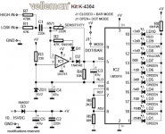
Or you could use an LM3915 moving dot meter, that would do the trick.
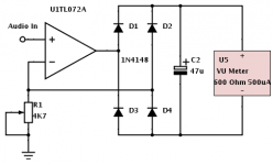
Why not just use a nice old fashioned analogue VU meter if you want to see the level of the signal in real time? It can be done with very few components and just one opamp (see attached).
Hope that helps.
Or you could use an LM3915 moving dot meter, that would do the trick.
Why not just use a nice old fashioned analogue VU meter if you want to see the level of the signal in real time? It can be done with very few components and just one opamp (see attached).
Hope that helps.
Attachments
Have an LED of varying brightness and then a peak/clipping LED. You can do that with 2 op-amps quite easily.
What I would like is for a yellow LED to be on from 0 to .8Vpeak to peak, a Green LED to be on from .8V to 1Vpeak to peak, and a red LED to be on above 1Vpeak to peak. Only one LED on at any time. So how would I go about doing this with logic gates?
Last edited:
Why not have a look at the LM39xx series of IC's, they do exactly what you require.
The LM3914 produces a linear scale
The LM3915 produces a logarithmic scale
The LM3916 produces a VU scale
The are ever so simple use and use very few external components.
The LM3914 produces a linear scale
The LM3915 produces a logarithmic scale
The LM3916 produces a VU scale
The are ever so simple use and use very few external components.
Last edited:
As already mentioned, the moving dot/led display IC should do it ! Or build a 3 OPA comparator that shorts out the Yellow & Green LED's transistors base resistors as the voltage moves up, with another transistor. The output of the Green Comp would short out the Yellow, & then the output of the Red Comp would short out the Green 🙂
I'm just not interested in using the LM39xx ICs for this project. Zero D, would it be too much to ask for a drawing? A picture is worth a thousand words, my imagination isn't all that good. 😀
I'm just not interested in using the LM39xx ICs for this project. Zero D, would it be too much to ask for a drawing? A picture is worth a thousand words, my imagination isn't all that good. 😀
The datasheets show you how the LMxxxx achieves what you are trying to do.
I'm sorry, I think you misunderstood. I don't want the 3915. I'm more looking for the comparator, base shorting version. I know of the 3915. I just don't want to go that way.
lm3915 VU METER
Hello
greetings i need a audio limiter to limit audio signal from preamplifier when it is more than 1 volt vu meter sensitivity can be adjusted by preset so
when signal is about 1 volt led will light up LED can be attached to LDR which can be attached to ground and pin no 3 of ic TLO72 is this idea possible to make a simple limiter
warm regards
Andrew😕
Attachments

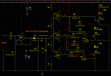
Hmm. You seem to be on the right track with the comparators but you'll need to drive them with a smoothed rectified version of the audio signal. The diodes on the op-amp outputs do not serve any purpose either, better to replace them with a resistor divider, perhaps 10K and 10K for each transistor. The circuit you've shown won't work at all unfortunately 🙁.
Hope that helps 🙂.
Hope that helps 🙂.
Just build the LM3915 circuit man. It'll give you a much better idea of what's going on, look better and won't cause any distortion to the input signal.
You're sorta on the right track, in some respects, but as has been said, it won't work as is !
Here you go ! The input is buffered & half wave rectified & smoothed, which is fine unless you want recording studio etc performance. You need to work out R4 - R7 so it gives you the voltage trigger levels you want at each stage.
The OPA's should be types that allow larger differentials between the + & - inputs than "some" will allow. TL074 would be fine.
Let me know how you get on, this time !
Are you using a Sim, or is it just drawing software ?
Attachments
Just a drawing. I've tried using LTspice before, but can't figure out what settings to use. I need to find some video tutorials on it.
Thanks, I really appreciate your help.
I also appreciate all the others as well.
Thank you all.
Thanks, I really appreciate your help.
I also appreciate all the others as well.
Thank you all.
- Status
- Not open for further replies.
- Home
- Source & Line
- Analog Line Level
- I Need A New Audio Input Indicator