I use Multisim. They have recently released this, free for a few years, version. http://www.diyaudio.com/forums/software-tools/263091-multisim-blue.html
A good tutorial on LtSpice is here http://www.diyaudio.com/forums/software-tools/260627-installing-using-ltspice-beginner-advanced.html
Have fun 🙂
A good tutorial on LtSpice is here http://www.diyaudio.com/forums/software-tools/260627-installing-using-ltspice-beginner-advanced.html
Have fun 🙂
I'm sorry, I think you misunderstood. I don't want the 3915. I'm more looking for the comparator, base shorting version. I know of the 3915. I just don't want to go that way.
I understand what you don't want.
But the LM39xx datasheet will show you how the ladder input to the comparators is implemented, you can use this idea in your design.
To get a bar type display, ie all the LEDs under the desired LED illuminating is easy, getting the undesired LEDs to extinguish can be achieved using logic gates.
These days most would implement a PIC processor.
Last edited:
Nice work Zero D, although a few improvements could me made?
The circuit won't have any sensitivity below about 0.6V due to the voltage drop of the diode. Perhaps use the 1 opamp inverting precision rectifier to improve this?
1K and 1uF, with 100K drain create a time constant of around 1ms for rise and 100ms fall which makes the circuit a quasi peak program meter, is this intended?
The LED resistors are 2K, this makes for just over 6mA of LED current. They'll be a little dim. I would have gone for 10-15mA of LED current.
Perhaps also drop the rails to +-9 V and make the LED resistor values 680R?
Of course it's it's all very well for me to sit here making criticisms behind my keyboard 😛.
Just thought I'd post this old 3-LED window comparator here for interest.
http://i81.photobucket.com/albums/j207/merlinblencowe/WindowLEDs_zpsaff623b6.jpg
http://i81.photobucket.com/albums/j207/merlinblencowe/WindowLEDs_zpsaff623b6.jpg
@ monty78pig
Thanx !
An OPA precision rectifier would be better, i agree. I expected the TC's to be ok, as when fed with a strong signal they would stay visable. Of course values could be adjusted to suit. I made the LED resistors 2K as they were 6.8K in his diagram. With highish effeciency LEDS's 2k would be fine. If not they could be lowered to suit.
Not even an OPA, just taking the feedback after the diode would improve performance. Also, when the comparators are 'off' the voltage at the transistor bases will be about -12V or so. Most small signal transistors can only take around 5 or so.
@ monty78pig
Another idea to overcome the diode forward bias, which i've done before, would be to give U1 gain. For eg, x 10. Then dimension R4 - R7 accordingly !
I've never had a problem in the past with similar circuits. But it's worth noting etc 😉 As you suggested earlier, lowering the PS voltage could help.
Actually the LED's could be powered directly from the OPA's outputs. With a suitable resistor. At least 10mA should be available, & i've done this a number of times previously. Still working fine after Many years 🙂
Another idea to overcome the diode forward bias, which i've done before, would be to give U1 gain. For eg, x 10. Then dimension R4 - R7 accordingly !
Most small signal transistors can only take around 5 or so.
I've never had a problem in the past with similar circuits. But it's worth noting etc 😉 As you suggested earlier, lowering the PS voltage could help.
Actually the LED's could be powered directly from the OPA's outputs. With a suitable resistor. At least 10mA should be available, & i've done this a number of times previously. Still working fine after Many years 🙂
If you increased your gain by 10 times then you'd be clipping once the signal reaches about 1.2 volts. Perhaps it would be best to design this circuit with a single supply rail?
I only suggested "For eg, x 10"
He only needs to register up to over 1Vpeak to peak, so clipping might not matter.
He only needs to register up to over 1Vpeak to peak, so clipping might not matter.
That's very true. But it'd be a little easier to make a full wave rectifier, or even just use fully discrete circuitry. That way you'd only need single supply.
You can't have it all, just choose most important specs.
LM3915 has it all in one package but you don't want it, a bunch of logic gates is fine, will cost as much as LM3915 , use lots more real estate and of course, "somebody" , will have to design it.
Not only the circuit but the PCB.
Good luck with that.
I suggest this very cheap and available solution, but leds light in a column, not one at a time. Can you live with that?
The voltage divider is just an example, set it to the trigger values you wish, you'll have to rectify Audio (simplest is with a germanium diode, still available) and your RC time constant should be 1 to 5 seconds, to be useful.
An externally hosted image should be here but it was not working when we last tested it.
Last edited:
A full wave rectifier would give an accurate voltage out. I alluded to that earlier when i mentioned a possible studio type circuit. It "seemed" it wasn't required in this instance.
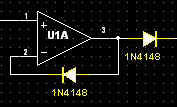
I've added an extra diode around U1A which better helps to overcome the FD. This increases the output voltage into the comparators. I would build it & feed a sine wave into it @ say 1kHz @ the voltages required, then test the output voltage on the capacitor. This won't be as much as the voltage in, but it doesn't matter as long as R4 - R7 are dimensioned to account for this. So the Yellow LED would still illuminate up to 800mV input, Green between that & 1V, & Red above that. Cheating i suppose, but who would know, apart from the builder !
You could increase the time the LED's stay on, by changing the capacitor to a higher value. I would try 10uf to start with. Whatever suits is the right one.
@ JMFahey
Nice, but he wants a dot display !
Attachments
- Status
- Not open for further replies.
- Home
- Source & Line
- Analog Line Level
- I Need A New Audio Input Indicator