Do a search on some threads for soundcard oscilloscope, I think it's been covered pretty well in diyaudio. The simplest voltage matching devices is just a pair of resistors to form a voltage divider, but there are more elaborate circuits also. I have a normal scope so I've never done it myself.
I think I better wait and get an oscilloscope. I saw some for 350$, and thinking I love diy electronics maybe I should get one.
I finished the preamp stage but I got a problem. At about half rotation of pot I get alot of distorsion at low freq. Am I getting too much gain? What shall I look for to have maximum level with no distorsion? Lower the gain or?
I finished the preamp stage but I got a problem. At about half rotation of pot I get alot of distorsion at low freq. Am I getting too much gain? What shall I look for to have maximum level with no distorsion? Lower the gain or?
Without a scope, what you can do, is download an mp3 of say 100Hz or 500Hz or 1000Hz sine wave. These are free. Play it through your computer (in loop mode) and connect the output from the soundcard to your amp, with a level of say 200mV RMS which you can measure with your multimeter. Some meters will read AC up to 1000Hz, I think most, but cannot be sure. Then measure the AC output of the first amplifying stage. Vrms out/Vrms in = the gain of the stage. For example, the input to your amp is 300mV rms. You get 9Vrms out from the first gain stage. Gain = 9/0.3 = 30.
Your amp will distort when the peak signal swing from the splitter is the same as the bias voltage. For example, with output tubes cathode biased at 11V, full power is developed when the splitter puts out 11V peak, or 22V peak to peak or 7.8Vrms. So you can see it easy to overdrive the amp with just one gain stage.
Your amp will distort when the peak signal swing from the splitter is the same as the bias voltage. For example, with output tubes cathode biased at 11V, full power is developed when the splitter puts out 11V peak, or 22V peak to peak or 7.8Vrms. So you can see it easy to overdrive the amp with just one gain stage.
I will try that. But, do you have any ideea why my voltage increases in time? I mean, after one hour of use it was ok, as at startup, but after about 3-4 hours it goes up from 300 to 330V. I even got one red anode... Shouldn't that be stable? The power tranny is a bit worm but that's all...
i tested with a 100hz sine wave. was 80mV at input rca and tested 1.8V at grill of el84. Couldn't test anywhere else on the way thou. that's 22.5 x factor. from the math I did last night it should have been about 17 but...pretty close 🙂 as well, how could I improve my bass? there's another problem, the speaker that I am using for testing purposes is in fact a bi-amp speaker, and I am using it in bridge mode between the 2 channels, furthermore it isn't very recommended since the mid-high channel is rated at 6ohm and the low channel at 8 ohm. Could this be a problem? the output tranny runs pretty cold
anyway I'm open to suggestions about the PI stage. I have some 6n6p 6n1p-ev and 6n2p-ev tubes lying around so I would built the best suited PI for those EL84's 🙂
I'm using a M-Audio Fast Track Pro for audio output and distorsion becomes noticeable at about 2 o'clock of the volume knob. That's about 3V AC measured with the MM on the g1 grid of one el84 (MM is pretty ok, UNI-T UT70B was about 100$ so I think it's reliable). Beyond that I get bass distorsion. A bit hard to know exactly because I only used the 8ohm bass input of the speaker and I do get mid+high sound as well and that gets very distorted anyway, but the bass goes nuts at around 2 o'clock of the knob. Any chance I could get crisp clear bass at maximum output of soundcard? I would change the first 2 stages gain+PI or build an integrated one. My output tubes are stuck at EL84 (RFT manufacture) or I might just swap them for 6p14p-ev when I get the chance. I red somewhere that el84 are really bad on bass and that 6p14p-ev are the best for that kind of work. I'm actually looking for a low-level rich bass sound. My room is about 20 square meters btw, not a very big place 😀
As well I'll get a Fostex fe206en driver soon so I could take that into account as well for final design. I know it's overkill for this little space but I have another weekend place that I stay and there I got more like 100 square meters in the living-room so I could use it there for better purpose. Maybe I'll get a SE for week place.
Last edited:
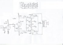
I see a couple of problems with that last schematic right off the bat. The 1 Meg grid leak resistor on the input stage is on the wrong side of the input capacitor. There is no ground reference for the tube which is a really bad thing. Also it is too large. According to the data sheet I have the grid circuit resistance should be a maximum of 500K. I would go lower than that to give some wiggle room.
sorry, I drew it on the wrong side of the capacitor. I changed it for a 330K one but the distorsion appears at the same volume
Last edited:
The 1M feeding the cathodyne is not needed, I would remove it. Where did it come from? Also the grid leak resistor of 820K on the cathodyne is too large as mashaffer pointed out. After fixing those things, and you still get distortion at low listening levels, I would try a different speaker or a different sound source.
I put that as a large grid stopper after I red the "Grid-Stoppers and Miller Capacitance" chapter from valvewizzard. I removed it also I adjusted the 820k resistor. I get the same distorsion at more than 2'oclock of the knob from the audio card. The pot from the amp is at max anyway. I wanted to have a clean sound with everything at max. The audio card was pretty expensive and I know it is very good, as well the speakers are Technics with low at 120W(music power) as it is written on the back of it. Maybe Ill wait for the new driver and see then how it performs. Untill then I'll turn down the volume a bit until it is clear. Thank you very much for your help!
Btw, I red somewhere that RFT EL84 tends to overdrive easily. Maybe I should try a 6p14p-ev meanwhile and see what happens. These RFT are NOS and had like 20 hours max on them since I started building the amp, maybe they aren't at their best yet.
Btw, I red somewhere that RFT EL84 tends to overdrive easily. Maybe I should try a 6p14p-ev meanwhile and see what happens. These RFT are NOS and had like 20 hours max on them since I started building the amp, maybe they aren't at their best yet.
Actually, a grid stopper IS a good idea, just not 1M and not on the "wrong" side. Use something like 1k, with the resistor right at the grid pin. The cathodyne grid leak then goes on the "far" side of the stopper.
More serious problem: with a pentode output stage and no feedback, the source impedance is really, really high- if your speaker is not designed for current drive, it will be quite boomy. The bass distortion will also be quite high.
More serious problem: with a pentode output stage and no feedback, the source impedance is really, really high- if your speaker is not designed for current drive, it will be quite boomy. The bass distortion will also be quite high.
damn! I drew that wrong as well 🙂) it was on the right side in reality but I have everything on a breadboard and when I drew it it was late night and I didn't pay very much attention. I'll put a 1k resistor just to be sure. After I detached from the details I realized that the sound has been very much improved since the beginning 🙂 and the distorsion is present for all audio range, everything distorts at max level but I will better try with a good speaker. Any suggestions? I am willing to pay max 200$ for one fullrange speaker. I was thinking at a Fostex FE206EN but if you have better ideas please do not hesitate. Thank you very much for all your help, I learnt alot from this, and I am very proud to declare this my very first audio amplifier (and it is on tubes too 😀 )
p.s. my speaker performs very good on it's own digital amplifier, much louder and crisp clear.
p.s. my speaker performs very good on it's own digital amplifier, much louder and crisp clear.
Last edited:
SY makes a good point. I hadn't noticed the lack of FB. I bet you will need either local or global FB in order to drive most speakers well. I am not sure how one would do local with a cathodyne directly connected to the outputs but maybe someone smarter than me would have a suggestion. Global of course is easy enough.
ok, now it might sound stupid but I have no ideea what global or local feedback is... got any nice tutorials on that? 🙂
Merry Christmas everyone!!!!
Merry Christmas everyone!!!!
To over simplify somewhat...
Negative feedback is when you feed a part of the output (inverted) back to an earlier point in the circuit to flatten frequency response, lower output impedance (with most implementations), reduce total distortion, and choke the life out of the sound (Just kidding 😀).
Global is around the whole circuit while local is around less than the full circuit (usually just one stage). There are some advantages to both approaches. Local is usually easier to avoid instability but global allows you to "correct" for linearities in all stages and the output transformer.
ok thx. Can I use the info here? The Valve Wizard
I just tried the speaker with it's original amplifier and it just blows out my tube amp hands down. But it's about 10 times more powerful anyway. All I need is no distorsion, the rest I'll get out from a high efficiency speaker.
I just tried the speaker with it's original amplifier and it just blows out my tube amp hands down. But it's about 10 times more powerful anyway. All I need is no distorsion, the rest I'll get out from a high efficiency speaker.
The Valve Wizard stuff is very useful. One thing to watch for is the input impedance also changes with FB as that site shows so you need to be sure that you don't load down the phase inverter. If you use local FB like that you would want it around the output pentodes.
Another thought that occurs to me is what power level are you at when you get the distortion. It is possible that those speakers are just too inefficient for this amp also.
Another thought that occurs to me is what power level are you at when you get the distortion. It is possible that those speakers are just too inefficient for this amp also.
0.4-0.6V input from the sound card. till 0.4 it sounds ok. that's about 60% of total rotation of the knob. it may be that's why I'll tell the final verdict when I get an efficient speaker. I have some reading to do now 🙂 any other sources to study besides ValveWizzard?
Yes but what is the voltage out of the amp at the point where distortion starts? Also I didn't realize what you were using for a source. The distortion may be coming from the sound card. If the solid state amp that you are comparing this amp to has higher gain (not power but gain) then you may not be going to as high an output from the sound card with the SS amp. Do you have a regular source (tape, CD, DVD etc) and preamp that you can use?
- Status
- Not open for further replies.
- Home
- Amplifiers
- Tubes / Valves
- I need a bit of help to fine tune my PP EL84 amp