hello people. this is my first time posting here. I got help from my local tube forum but seems no one can help me further so I am going international 😀
I started from a small scheme of only 1 6n1p tube as phase inverter and 2 el84 output tubes and I ended up with a 9 tube stereo amp 😱
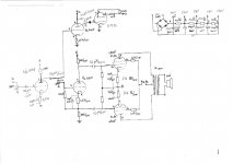
Ok, so I opted for a 6n6p preamp stage, each triode for a channel, next stage is the phase inverting stage, one triode from 6n1p I use for driver of the 2 el84 output tubes, and the other triode for the EM84 meter tube. The input tranny is a toroidal 220V in with 3 secondaries: one of 240V with 400mA for the amp itself and 2 of 6.3 each 6A for the filaments. I opted for a DIY scheme that someone helped me with. The output trannys are made custom from a friend, each 15W output 6k6 impedance for 8 ohm speakers. They are very good built, many dudes used his transformers and were very happy. I attached the scheme below with the details. I must note that I am a beginner, this is my first project and it turned out real nice despite my expectations 😀 The sound is clear and just perfect. The downside are my speakers. They are bi-amped, no internal crossover. So I had to make a bridge to get full range. Problem is that low is 8 ohm and mid+high are 6ohm. Anyway the output transformer is quite cold, sound is clean so I don't worry. Setup was not so expensive, the whole project cost me about 200$ for the electronic components the transformers and the tubes. The case is yet to come thou. Speakers are from an old Technics system with the bass speaker about 17 cm diameter, no real charm but they sound ok. So I don't worry about any damage, if anything is to happen I don't mind much, it's my first project after all 😀
Anyway, I did some measurements and, if at first with only 6n1p as driver and 2 el84 as output tubes the values I got were pretty perfect now when I added the preamp stage and em84 meters everything is kinda mixed up. I am going for 15W output per channel. The electronic components used are among the cheapest possible here, and it's only what I found in local shops. After I finish the whole thing I'm thinking of ordering some quality coupling capacitors and such. And only after that I will go for the final touch, the actual "house" for everything. I will add some measurements below:
anode of el84 has 270V and a current of 44mA.
cathode has 9V
anode of driver 6n1p has 158V on anode and draws 1.1mA. On cathode there are 40.5V
the anode of preamp 6n6p has 110V with 3,7mA current draw. on cathode I got 5.4V.
pins 7-9 for EM84 have 52V and pin 6 has 147V. it's not at brightest but I can see it. the lines are not touching in the middle, they are 1/3 of total lenght, and I only get movement at high audio level. at normal listening power they almost stand still. This would be one of my problems. The other is the power supply stage. Normally it has been designed for something else but I kept upgrading the scheme and now it isn't delivering enough juice. Not that 400mA wouldn't suffice, the are good for both channels and still got some room. But the voltages are not quite right. Between point E and A I had a choke but since I didn't find any I replaced it with a 150ohm resistor. Anyway I have no hum at all so I considered I don't need one. Now I noticed that I got 313V in the first point after the rectifier bridge so I though I could use that. That's why that's the first contact point, before A. Anyway feel free to recommend any adjustment, but mostly I would like to keep the setup this way. Only for bit adjusting of resistors and such so I get the most out of every tube. As I am aware 6n1p performs best at 200V on anode and 50V on cathode. 6n6p is arround 120-140V on anode, the EM84 needs about 250V before the resistors on 7 9 and 6 pins. And the EL84 does good at about 40-45mA current draw on anode. So ...output stage seems ok but I think I could tweak a bit the preamp and driver. As well I would like to fix the EM84. Can it be adjusted so that it moves the same at low and high volume? Thank you very much for reading my problem, home I get some answers here, seems that my dudez are either too busy or too arogant for my noob problems.
forgot to mention that the preamp/driver stage don't neet 5W resistors but that was later found out. And the cathode resistors for el84 are 177ohm because thats what I actually measured in the series ones that I build to get close to the 180ohm value. I will try to get it closer to 180, that would "almost" make it class A if I'm not mistaken, and going towards 270ohm I go for AB.. At least that's how someone explained to me.
I started from a small scheme of only 1 6n1p tube as phase inverter and 2 el84 output tubes and I ended up with a 9 tube stereo amp 😱
Ok, so I opted for a 6n6p preamp stage, each triode for a channel, next stage is the phase inverting stage, one triode from 6n1p I use for driver of the 2 el84 output tubes, and the other triode for the EM84 meter tube. The input tranny is a toroidal 220V in with 3 secondaries: one of 240V with 400mA for the amp itself and 2 of 6.3 each 6A for the filaments. I opted for a DIY scheme that someone helped me with. The output trannys are made custom from a friend, each 15W output 6k6 impedance for 8 ohm speakers. They are very good built, many dudes used his transformers and were very happy. I attached the scheme below with the details. I must note that I am a beginner, this is my first project and it turned out real nice despite my expectations 😀 The sound is clear and just perfect. The downside are my speakers. They are bi-amped, no internal crossover. So I had to make a bridge to get full range. Problem is that low is 8 ohm and mid+high are 6ohm. Anyway the output transformer is quite cold, sound is clean so I don't worry. Setup was not so expensive, the whole project cost me about 200$ for the electronic components the transformers and the tubes. The case is yet to come thou. Speakers are from an old Technics system with the bass speaker about 17 cm diameter, no real charm but they sound ok. So I don't worry about any damage, if anything is to happen I don't mind much, it's my first project after all 😀
Anyway, I did some measurements and, if at first with only 6n1p as driver and 2 el84 as output tubes the values I got were pretty perfect now when I added the preamp stage and em84 meters everything is kinda mixed up. I am going for 15W output per channel. The electronic components used are among the cheapest possible here, and it's only what I found in local shops. After I finish the whole thing I'm thinking of ordering some quality coupling capacitors and such. And only after that I will go for the final touch, the actual "house" for everything. I will add some measurements below:
anode of el84 has 270V and a current of 44mA.
cathode has 9V
anode of driver 6n1p has 158V on anode and draws 1.1mA. On cathode there are 40.5V
the anode of preamp 6n6p has 110V with 3,7mA current draw. on cathode I got 5.4V.
pins 7-9 for EM84 have 52V and pin 6 has 147V. it's not at brightest but I can see it. the lines are not touching in the middle, they are 1/3 of total lenght, and I only get movement at high audio level. at normal listening power they almost stand still. This would be one of my problems. The other is the power supply stage. Normally it has been designed for something else but I kept upgrading the scheme and now it isn't delivering enough juice. Not that 400mA wouldn't suffice, the are good for both channels and still got some room. But the voltages are not quite right. Between point E and A I had a choke but since I didn't find any I replaced it with a 150ohm resistor. Anyway I have no hum at all so I considered I don't need one. Now I noticed that I got 313V in the first point after the rectifier bridge so I though I could use that. That's why that's the first contact point, before A. Anyway feel free to recommend any adjustment, but mostly I would like to keep the setup this way. Only for bit adjusting of resistors and such so I get the most out of every tube. As I am aware 6n1p performs best at 200V on anode and 50V on cathode. 6n6p is arround 120-140V on anode, the EM84 needs about 250V before the resistors on 7 9 and 6 pins. And the EL84 does good at about 40-45mA current draw on anode. So ...output stage seems ok but I think I could tweak a bit the preamp and driver. As well I would like to fix the EM84. Can it be adjusted so that it moves the same at low and high volume? Thank you very much for reading my problem, home I get some answers here, seems that my dudez are either too busy or too arogant for my noob problems.
forgot to mention that the preamp/driver stage don't neet 5W resistors but that was later found out. And the cathode resistors for el84 are 177ohm because thats what I actually measured in the series ones that I build to get close to the 180ohm value. I will try to get it closer to 180, that would "almost" make it class A if I'm not mistaken, and going towards 270ohm I go for AB.. At least that's how someone explained to me.
Attachments
Last edited:
forgot to mention that the preamp/driver stage don't neet 5W resistors but that was later found out. And the cathode resistors for el84 are 177ohm because thats what I actually measured in the series ones that I build to get close to the 180ohm value. I will try to get it closer to 180, that would "almost" make it class A if I'm not mistaken, and going towards 270ohm I go for AB.. At least that's how someone explained to me.
This sounds bad 🙂 well I'll check it tomorow. I just want to use those tubes transformers and scheme in the most part. Would be kinda awfull to start from scratch again. Anyway it sounds real good and loud with no distortions noticeable by me. I must say that I don't have a deep bass but still, would like to make it better. So, I must change the cathode resistors and anode voltage for el84 right? I would like it in class A or near as possible
I am prepared to change most passive components as long as I get the final output near 15W per channel, and use the em84 meter (or any meter for that matter as long as it's nicer than em84).
Why should I have a resistor from grid to ground?
Does this scheme seem so bad? It sounds nice to me but then again, I don't have much experience in hi-fi 🙂 I'm also thinking of some FE206 fr speakers for this system. I don't have more than 200$ for the drivers and I wanna build my own enclosures. I'm a diy freak! 😀
You have overcomplicated a simple idea imho and yeah, the scheme as built mitigates AGAINST bass... Nothing that cannot be fixed though.
I added a 330k resistor from 6n6p grill to ground. I put back the 150ohm resistor between B and C points, and added an extra 150 ohm between E and A, and I also changed the cathode resistors of el84 from 177 ohm to 147.5 ohm. It's the closest resistor I could get now. I got the following values:
el84 - 265V on anode and 47mA current draw on one and 48mA on the other tube.
6n1p - 216V on anode with 1.63mA current draw and 60V on cathode
6n6p - 127V on anode with 3.4mA current
The voltages from the supply are as follows:
E - 313V
A - 274V
B - 274V
C - 273V
D - 270V
The EL seems pretty close to the A class in data sheet. My output tranny is somewhere near 5.3K as the friend who made it told me today. Are these values ok for the output tubes?
What shall I do next?
hmmmn - the opts are NOT optimal for the EL84. THey should be around 8k a-a.
THe EL84s do not have sufficient voltage across them (anode to cathode) to operate optimally. They are biased at just over -7 volts. They should be closer to -12v.
I don't think your power supply is going to get you there - you are going to need to achieve about 320V at the primary centre tap of the opt with cathode bias, or 305V if you go to fixed bias on the finals (no cathode resistors). In which case your power supply will JUST get there, maybe.
I don't think your voltage amp (6N6p) is capable of delivering the gain required to drive the cathodyne splitter to achieve full voltage swing on the EL84s. It needs to be able to put out at least 50Vpp, preferably more. In any case, at 127V on the anode at idle you are waaaay down in the non-linear area of its operating curves. Its the wrong tube for this front end duty.
I haven't looked at the set-up of the splitter because frankly, I'd ditch it and change topology to a simple 2 stage - ltp to finals.
I know this looks pretty negative but take it as a learning experience! All is not lost, and you can remodel the circuit to acheive close to what you are looking for.
How many taps on the secondary winding of your output transformer, and what is the nominal impedance for each tap?My output tranny is somewhere near 5.3K as the friend who made it told me today.
And, welcome to diyAudio!
John
There's 4 main problems in your schematic.
1. No grid leak resistor on pin 6 the 6N6P. Either fit a 500K or something from ground to pin 6, or eliminate the 0.1uF cap.
2. The 220K pot feeding the 6N1P will compromise the 6N1P's phase splitter action and is not required - eliminate it, it has no use. That 220K pot is evil in that position.
3. The other 6N1P half has no anode resistor so cannot generate an output voltage to drive the EM84.
4. The grid bias conditions for each half of the 6N1P cannot be shared, so you need a coupling cap for each to isolate the grid bias conditions for each half 6N1P. That means, the 6N1P driving the EM84 cannot share with the 6N1P driving the amp, they have different bias requirements. Use one cap to drive the lower 6N1P, and another cap to drive the other 6N1P.
I recommend using 6N1P for the first gain stage and the cathodyne phase splitter, it's a really good tube to work with and very forgiving. I would disconnect the EM84 part until you are happy with the amp, then reconnect it and go from there. You are doing a good job for your first amp, if you want to read up on some theory that is user friendly, find the valvewizard site and read up "triode gain stages".
Don't worry about voltages too much, get the circuit right first. The cathode resistors for the output tubes need to be 200 ohm plus. Don't worry about the 5K3 OPT impedance, should be fine.
Hey guys, thank you so much for the info. I will go back to the drawing board, I'll disconnect the 6n6p and the EM84. I'll read some more on cathodyne phase splitter and will come back with some info. The power transformer has a 240V 400mA output on one of the secondaries, that will get me about 339V DC after rectifier right? So can I use it for the whole setup? Finally I'm looking for a preamp stage, phase inverter stage, final output stage and would surely love a EM tube, whichever is nicer. The heater secondaries are 6.3V 6A each so there I shouldn't have a problem. But this setup will be for both channels so ... if it isn't enough (I like to have a 30% more room just to be safe) then I would order another one, takes about 2 days to get it and the company is makin' it custom as I want. And being a toroidal helps me a lot. Price is ok as well, the one that I already have costed me like 35$.
How many taps on the secondary winding of your output transformer, and what is the nominal impedance for each tap?
And, welcome to diyAudio!
John
There's only one secondary for 8ohm speaker. No taps.
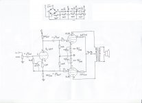
I took apart everything from the breadboard and I made the whole setup again. I attached the scheme. It's only phase inverters for El84 using one triode only from 6n1p for cathodyne phase splitter. I also changed some resistors here and there to tweak it a bit. After all was setup it ran perfect on the first try. I mean, no hum and clear music at low level. Couldn't test more because it's like 4 o'clock in the morning and I got some sensitive neigbours 🙂
Anyway here are the measurements:
supply points:
A-316V
B-315V
C-309V
El84 - anode 302V
- cathode 10.7V
- Rk 221 ohm (and that I got from 2x150 ohm resistors in parallel plus another one separate in series 🙄 , didn't have any other option atm)
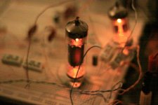
So the current is 48mA for one and 49mA for the other (the one with more current has a red spot on the plate, barely noticeable but still it's there, the other one is ok. I attached a photo of the effect)
6n1p - 1/2 only
- anode 262V
- cathode 55V
- Rk 3.3k (same, that was the closest value I had at hand)
- current 1.5mA
Before I continue to make the preamp stage out of the remaining triode in the 6n1p tube I would like to know if the present setup is ok or do I need to work at it furthermore
Thank you very much!
P.S. the picture of the EL84 tube is actually made in almost dark, there seems to be much more light than actually was, it was made at ISO6400 at F1.8 aperture 😀 so the spot isn't that noticeable as in the picture, it's very faint to the naked eye, the camera makes it look more...bad 🙂
Attachments
I studied the ValveWizard tutorial The Valve Wizard
and the 6n1p-ev datasheet
http://www.mif.pg.gda.pl/homepages/frank/sheets/113/6/6N1PEV.pdf
and I am completely lost. I just cannot figure out the Rb value. I get weird results like 47k... I stood up all night trying to understand but it's hopeless. The graph that I have for the triode is in 10mA increments and the result is wrong in the end. If someone could tell me how to calculate that resistor I would very much appreciate it. As well as how do I measure that -2V bias (or -4 depends on datasheet) to see if I got it right in the end. Because I suspect that the triode isn't phase splitting as it should
p.s.
I think that with Rb=2.2K the red spot on one of the el84 is less obvious. with Rb=3.3k the spot was brighter.
Last edited:
I just got the Rb from calculations! 😀 it came out pretty evil 🙂) 666 ohms. I will try tommorow to see what are my results
Good idea to make it simple and go from there 🙂
The red-plate of the EL84's is controlled by the size of the EL84 cathode resistor, nothing to do with the cathodyne. With 48mA and 300V you have power dissipation of 300 x 0.048 = 14Watts, that is a bit too much. If you put in a 5W 270 ohm cathode resistor for the EL84 that would make it safe. A bigger value cathode resistor will raise the cathode voltage which means the grid bias voltage will be more negative compared to the cathode, and this will reduce the current through the valve, that is what bias does, it controls the amount of current through the valve by setting a starting point from where current can increase and decrease when music is played.
The cathodyne by itself will not amplify the signal going into it, the gain is close to one, so the amp won't make much power just as it is, but maybe enough to have a good listen. For the amp to make full power the peak to peak voltage swing from the cathodyne needs to be twice the bias voltage of the EL84. An example: your EL84 bias voltage is -10.7V, for full power you need 21.4V peak to peak from the cathodyne outputs, or about 7.5V RMS.
DC-coupled cathodynes are fairly popular for EL84 hifi amps, they might be worth looking into too, although the AC-coupled also has its advantages. The Simple PP by tubelab.com is a good example, also the Red Light District amp by SY, a mod on this forum. I have an amp running 6N1P and DC-coupled cathodyne if you are interested in some ideas in that direction.
The "triode gain stage" pdf is here . Its 30 pages but is really good stuff.
Hope you enjoy your experiments, its a fantastic way to learn, a mix of practical and theory. I often do the practical first and then try to suss out the theory, to understand why it sounds so bad or so good 😉 Theory without any practical just doesn't work for me.
EDIT: good 6N1P data here: http://klausmobile.narod.ru/testerfiles/6n1p.htm
Last edited:
I managed to get many different values resistors so I don't run out of options later 🙂
I changed Rk of el84 to 270 ohm and I got the following results
285v on anode
10.5v on cathode
35.5mA on anode of each tube, they draw the same amount now
I put Rg 680 ohm for 6n1p and got
205v on anode
90v on cathode
2.75mA on anode
A=301v
B=298v
C=295v
Before proceding to the preamp stage I'd like to know if my actual measurements are ok. Valvewizard is a great source of info! Thank you for that
Where can I read about the difference between those two tipes of coupling? I'd rather stay on actual course, maybe change the power supply transformer if I can't get enough juice out of it. I very much like this simple design, but in the end I don't worry much about the watts as I care for the quality of the sound. I'm thinking of getting 2 Fostex FE206EN full range speakers to go with the amp. I'l DIY the case for them, I saw alot of detailed instructions for that. So if there is good info on DC vs AC coupling then I might reconsider if DC is best for quality. Sorry for all the trouble but I want to learn how to make a tube amp from scratch, I don't like just to follow a schematic, I wish to fully understand it
Last edited:
There are some good old books on-line for free, Crowhurst and Cooper High Fidelity Circuit Design and Radio Designer Handbook 4 are just a couple.
http://www.diyaudio.com/forums/tubes-valves/38278-line-tube-learning-newbies.html
If you can get your hands on an oscilloscope or use your soundcard to do effectively the same, it may speed up your learning curve as you can "see" where a circuit runs out of headroom or is not running optimally. This would help a lot in understanding gain stages, phase splitters, screen grid current, and measuring the output of the phase splitter to see if it is comfortable in driving the output tubes to full power, and seeing what happens when the output tube grids approach zero volts.
The basic formulae V = IR and Power = VI are your best friend. In your circuit, current flowing in the 6N1P is 90V/33000 ohms = 0.0027A = 2.7mA. The power dissipated in the 6N1P is (205V-90V) * 0.0027A = 0.31W which is well within maximum dissipation. The power dissipated in the EL84 is (285V-10.5V) * 0.0355A = 9.75W which is safe, (some people like to run them "hotter" but let your ears be the judge).
Another thing to be extremely aware of is the profound effect the screen voltage has on the tube characteristics. Those 2K2 screen grid resistors could drop around 44V at 20mA during peaks, maybe more, I haven't actually ever measured peak screen current on an EL84. This will have an effect on the sound. You will probably hear differences in the sound using 100 ohms, 500 ohms, 1K and 2K2 in this position.
I just finished the first chapter in preamp stages, quite enlightening. I made the same calculations earlier today and I concluded as acceptable 🙂 Today I got 6p2p-ev for more testing. Tommorow I'll build the preamp stage and would be great if I could measure the output somehow. I got a M-Audio Fast Track Pro soundcard, is there any way I can use it as an osciloscope?
Thank you very much.
Thank you very much.
Ok, I saw how to use the soundcard as an oscilloscope but, how do I limit the voltage so I won't burn the soundcard? I have a LM317 but I saw that the montages used for it involve some resistors and capacitors. Wouldn't those components alter the quality of the wave?
- Status
- Not open for further replies.
- Home
- Amplifiers
- Tubes / Valves
- I need a bit of help to fine tune my PP EL84 amp