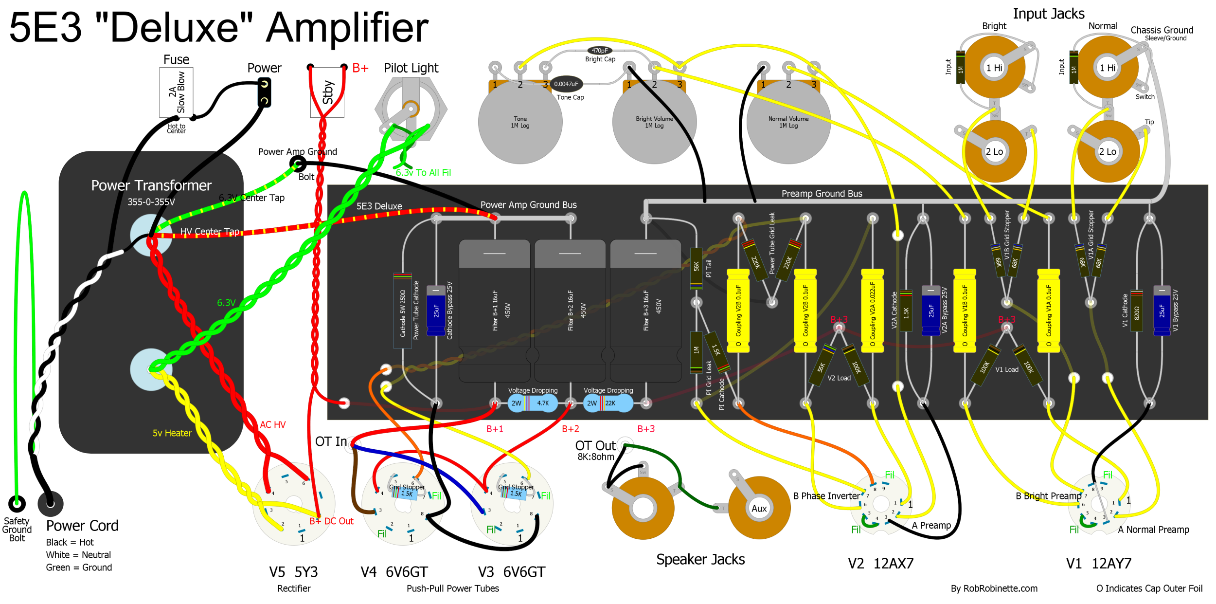
In a perfect world the fuse would be wired before the switch, and both would be on the Live side of the AC.
An externally hosted image should be here but it was not working when we last tested it.
Last edited:
C5 isn't needed if a polarized 2 conductor cord is used - remove it.
C5 is the "Death Cap" which MUST be removed on any old amp that has one present. If it is shorted or leaky (common with old wax caps) one side of the AC line will be connected directly to your guitar or microphone.
Just make sure the wide blade of the cord's plug is wired to SW1, the switch.
NO, put a 3 wire cord on the amp! Old power transformers with paper insulation can absorb moisture and become leaky, or shorted yet still apear to work properly. There is no guarantee that EVERY outlet the amp will be plugged into for the rest of it's life will be wired correctly. Have you seen the rats nest of cords and power drops used in some live performance situations. Back in the 70's I carried one of those neon bulb testers to every live performance situation and tested the power. Quite a few were miswired or had no ground.
Here is a quote from a post I made 10 years ago:
In most of the world one side of the mains or the center of the mains is connected to an earth ground. That makes one or both sides of the mains HOT (120 volts +) with respect to ground. Omit the isolation transformer and you DIRECTLY CONNECT this hot circuit to the ground circuit of your amp. Yeah there might be a rectifier, choke or other component in series, but it doesn't matter. Now the ground circuit of your amp is DIRECTLY CONNECTED to your guitar, turntable or CD player. This is electrically equivalent to taking your guitar cord and plugging it into one terminal of your wall (mains, line or whatever) socket. Would you do this?
Lets say you still don't understand, lets say that the microphone is grounded, and your guitar is hot with 120 or 240 volts, you are all sweaty because you are jumping all over the stage, when you touch the mic stand with one hand while your other hand is still on the guitar. YOU ARE TOAST! Now Google "Stone the Crows" and you will see that this is exactly how the lead guitar player was killed! Don't even think about it.
I just tested. It's not. I'm not sure who to trust. You or Kevin.
Listen, I've been a professional servicer for decades now.
And along with that, I've adhered to strict electrical codes to prevent liability issues. (who wants to get sued by the customer for bad/improper servicing?)
First off, that amp is wired goofy. - the fuse AND the power switch should really be wired in series on the same leg of the power transformer - with the wide blade side of a polarized cord.
The neutral side then should be wired to the other side of the transformer.
That cap, C5, preferrably an X2 cap, can also be wired from circuit ground to the neutral side of the cord if any hum/static issues are noticed.
THAT, in fact,..... is proper electrical code conformity, and eliminates any shock hazards.
Follow that procedure and you shouldn't have any future problems.
wiseoldtech, you are giving the OP incorrect information.
The WIDE blade on a 2-wire AC plug is the NEUTRAL, not the HOT.
Besides that it's a moot point since he should be using a 3-wire plug as previously recommended.
The WIDE blade on a 2-wire AC plug is the NEUTRAL, not the HOT.
Besides that it's a moot point since he should be using a 3-wire plug as previously recommended.
Listen, I've been a professional servicer for decades now.
And along with that, I've adhered to strict electrical codes to prevent liability issues. (who wants to get sued by the customer for bad/improper servicing?)
First off, that amp is wired goofy. - the fuse AND the power switch should really be wired in series on the same leg of the power transformer - with the wide blade side of a polarized cord.
The neutral side then should be wired to the other side of the transformer.
That cap, C5, preferrably an X2 cap, can also be wired from circuit ground to the neutral side of the cord if any hum/static issues are noticed.
THAT, in fact,..... is proper electrical code conformity, and eliminates any shock hazards.
Follow that procedure and you shouldn't have any future problems.
I am deducing from your post that the wide blade is the hot blade.
But google tells me:
wide blade is neutral and white in color
thin is hot and black
And you say that neutral does not connect to the fuse/switch in series.
Can you explain what I am missing here?
Yes, the wide blade is definitely neutral, narrow blade is hot. The fuse and switch connect to the narrow (hot) blade.
Take care,
Doug
Take care,
Doug
\In a perfect world the fuse would be wired before the switch, and both would be on the Live side of the AC.
An externally hosted image should be here but it was not working when we last tested it.
Thanks so much. This is exactly what I did.
wiseoldtech, you are giving the OP incorrect information.
The WIDE blade on a 2-wire AC plug is the NEUTRAL, not the HOT.
Besides that it's a moot point since he should be using a 3-wire plug as previously recommended.
Opps, indeed, my mistake!
The narrow blade is the "hot" side.
My morning coffee didn't kick in yet.
Opps, indeed, my mistake!
The narrow blade is the "hot" side.
My morning coffee didn't kick in yet.
Thank you so much for responding. I can rest easy now the mystery is settled.
And thank all of you for helping me with this. This community is so giving and thoughtful! I appreciate all of you!
It's nice to understand the mystery (and I write as a person who's spent his whole life trying to understand things as completely as possible), but this is a case where, no matter what the mystery, the bottom line simply must be adhered to. And the bottom line, when it comes to guitar amps, is just say "NO!" to two-wire mains cords!I can rest easy now the mystery is settled.
As Tubelab has said repeatedly, it MUST be a 3-wire cord, with ground properly bonded to the metal amp chassis.
As Mr. Miyagi from the cheesy old classic 1980s classic "The Karate Kid" might have put it, "Two-wire cord no can defense!" 🙂
Two-wire AC mains cords are still legal, but only for "double insulated" products that put a continuous unbroken insulation barrier between user and product. A guitar amp does not qualify.
(However, if your guitar had an onboard wireless transmitter, and your amp had a built-in matching wireless receiver, sealed inside an insulating enclosure, then it might be okay.)
-Gnobuddy
> C5 isn't needed if a polarized 2 conductor cord is used
The amp will work but HUMM/BUZZZ bad if wired 2-prong and no ground cap. Guitar amps "need" a lowish-Z path to the average electric hum potential in the room. Before wide use of 3-pin outlets, this was commonly a capacitor.
And FWIW: a healthy 0.05u cap is "legal" in the sense that at 117V you probably won't die of the shock. (Unless the string tingle makes you jump, fall off the stage, hit your head.) The problem is that these caps do NOT stay healthy forever. See another thread in which very similar old caps have decayed to high leakage. A dead-short failure is also common. (The 0.1u cap in this amp is "too large" under the electric codes I know.)
The point about SOLID grounding of chassis, whenEVER possible, is very valid for the reasons cited. Young transformers seldom break-down (it happens) but all transformers will "eventually" break down. Good one may be many decades. Low-Price amp transfos, not so long. It is generally preferable to kill the OT or a fuse than to kill the user.
Yes, Hi-Fi rigs often work with no path to wall common; guitar amps usually buzz. (I have not explored the "why". Long cables with poorly shielded parts on the far end?)
Last edited:
That, plus the guitar amp has got a very high-impedance input with a good amount of gain in it.Yes, Hi-Fi rigs often work with no path to wall common; guitar amps usually buzz. (I have not explored the "why". Long cables with poorly shielded parts on the far end?)
BTW, a proper Death Cap replacement would in fact have to be Y rated (e.g. Y2), not just X rated. Although 47n still seems a tad big to meet leakage current requirements, I'd say it should be more like 10n for 115V mains. 4.7 nF is a typical value in USB chargers.
(Having a proper Y cap also is what may separate a quality USB charger from a dubious cheapie. Watch Big Clive or DiodeGoneWild take apart a few of these, and you'll see some of the typical screwups - aside from skimping on real safety capacitors, it's PCB layouts with marginal to unsafe minimum primary / secondary isolation distances, and transformers with poor isolation between primary and secondary. Some scary stuff out there.)
Last edited:
Yes, Hi-Fi rigs often work with no path to wall common; guitar amps usually buzz. (I have not explored the "why". Long cables with poorly shielded parts on the far end?)
That, plus the guitar amp has got a very high-impedance input with a good amount of gain in it.
Both valid, but stage lighting, especially some of the older incandescent stuff with triac controlled dimmers pump a lot of line frequency noise with ragged edges and lots of HF harmonics into the air and power lines. It is not uncommon to have the lighting power bundled with the sound power, or even see one common power source for both.
take apart a few of these, and you'll see some of the typical screwups - aside from skimping on real safety capacitors, it's PCB layouts
We had the "safety cap" explode twice in some HP power supplies in our lab at Motorola. Both times I simply snipped out the remains of the cap, and the power supplies worked fine. I did give one of the exploded caps to the Agilent sales rep, who said that it had happened before....they were 20 year old power supplies......
Caps go bad, even good ones in expensive stuff. As stated some of the stuff out there today, especially those $5 phone chargers, is truly hazardous junk. I now use a $15 power box that has 6 line voltage surge suppressed outlets, and 5 USB outlets, and there is continuity from all of the grounds to the 3rd prong on the power plug.
Several years ago I got a nasty shock from my old Toshiba laptop when I plugged in a USB hard drive. It had a two wire cord on the typical power brick. The severity of the shock told me that it wasn't leakage, but a direct short. We were vacationing in Florida at the time so my attempt to open the brick with a hammer left it too far gone to see an obvious flaw. A new brick fixed the problem. Most new laptops have a 3 wire cord on the brick......there has to be a reason for this!
Last edited:
Some modern power supplies have a capacitor filter that consists of two similar capacitances, with one connected between Live and Chassis and the other between Neutral and Chassis. When I build my first and only switching power supply, I used this kind of filter. However, I was always concerned about the filter capacitors failing, and utimately, I removed this filter. I replaced the capacitors with a two coil inductor which is only sensitive to unequal Live and Neutral currents. This has the ability of presenting an inductive reactance to asymmetric interference.
An Anecdote:
I had a online UPS which employed full wave rectification of mains, and here, the voltage is 230V AC. When it failed, I opened its box, and to my amazement, I found it had a split power supply of +/-330V DC. This means, a total of 660V DC. Needless to state, I abondoned the repair for safety reasons. With 8 large electrolytic capacitors each charged to 330V DC, a short can result in injury, as many conductors will instantly vaporise. I remember, it had two chunky IGBTs which where shorted.
Last edited:
What you are doing is known as "common mode choke" and has similar effect in the filtering, but in a different manner. Switching currents flowing through the transformer's intra-capacitance from primary to secondary need to return to the primary through those capacitors, usually very larger than the former. Avoiding those caps can cause the SMPS to start oscillating and radiate the RF from the secondary side via the output cables. It is usually needed both, common mode choke and earthed caps.
Some modern power supplies have a capacitor filter that consists of two similar capacitances, with one connected between Live and Chassis and the other between Neutral and Chassis.
This is only so-so for reducing AC hum, and *puts the chassis at 60VAC*. Musicians have complained to me about this. (It was not my PA but a film-sound mixer tapped into my system.)
I replaced the capacitors with a two coil inductor which is only sensitive to unequal Live and Neutral currents. This has the ability of presenting an inductive reactance to asymmetric interference.
This will reduce RF hash but NO effect on line-freq hum/buzz.
This is only intended for RF EMI suppression anyway, and I would not be surprised if it had originated in someone just using an IEC Class I filter topology and basically removing the PE connection to make a Class II supply at some point. Suffice it to say that this is not an ideal way to make a mains filter. One reason why I don't like 2-prong wall wart style switch-mode supplies much.This is only so-so for reducing AC hum, and *puts the chassis at 60VAC*. Musicians have complained to me about this. (It was not my PA but a film-sound mixer tapped into my system.)
Years ago you really had to watch out for this with some (inkjet) printers. They could make some nasty sparks here in 230 V country if you attempted to connect them with power already plugged in. Clearly there was "a bit more" filter capacitance going on there.
The mentioned switching power supply has nothing to do with PA amplifiers; it was built in 1992 to serve as a bench power supply.PRR said:This will reduce RF hash but NO effect on line-freq hum/buzz.edbarx said:I replaced the capacitors with a two coil inductor which is only sensitive to unequal Live and Neutral currents. This has the ability of presenting an inductive reactance to asymmetric interference.
The idea of putting such a filter to filter the mains from RF generated inside the SMPS, was taken/learnt from other SMPS schematics. However, with 230V AC, and in the event of a bad connection to Neutral, the chassis would effectively be at 230V AC, albeit the current possible being a few milliamperes. My concern was, the fact, dielectric insulators are made as thin as possible to maximize the capacitance per unit volume, and a very thin isolating insulator, is not at all ideal as a shock hazard protection.
Gnobuddy,It's nice to understand the mystery (and I write as a person who's spent his whole life trying to understand things as completely as possible), but this is a case where, no matter what the mystery, the bottom line simply must be adhered to. And the bottom line, when it comes to guitar amps, is just say "NO!" to two-wire mains cords!
As Tubelab has said repeatedly, it MUST be a 3-wire cord, with ground properly bonded to the metal amp chassis.
As Mr. Miyagi from the cheesy old classic 1980s classic "The Karate Kid" might have put it, "Two-wire cord no can defense!" 🙂
Unfortunately, Mr. Miyagi would also have to say "Three-wire cord no can defense!" against a RPBG (reverse polarity bootleg ground) grounded 3-wire outlet. RPBG are most common in remodels of buildings converting two wire installations (common in wiring installed before 1965) two "grounded" three-pin outlets.
This type of miswire could easily be done by anyone "before they had their morning coffee" as evident in post #19 in this thread where "wiseoldtech" forgot that "it's the little guy that gets you".
A RPBG will test "OK" with a 3 light plug in tester, and even with a VOM.
Testing for a RPBG can be done with a non-contact voltage tester (NCVT). When this tester is used on a properly wired outlet, you’ll hear a beep or see a light only when its tip is inserted in the “hot slot” of an outlet. However, when this type of tester gets near the front or ground contact of an RPBG miswired outlet, it typically beeps/lights from inches away, because the internal ground strap in the outlet will be biased to 120V, which provides a large electrified surface area.
Failures in Outlet Testing Exposed | Electrical Construction & Maintenance (EC&M) Magazine
As a sound engineer, in the "old days" I always used the fingers of one hand to test for potential voltage between a guitar ground (strings) and PA ground (microphone Pin 1/ case), but a NCVT can save you from that tingle when outlets are mis-wired, or the "death cap" has started to dry up.
The bottom line is don't assume a 3-wire plug on your guitar amp will keep you safe, always test between the amp chassis/guitar strings and any thing else you might make contact with.
Art
Attachments
Last edited:
- Home
- Live Sound
- Instruments and Amps
- I got shocked from this old tube amp. What do I need to do to fix it?