Here's the DS115-8 (4") data sheet: https://www.parts-express.com/pedocs/specs/295-424--dayton-audio-ds115-8-specifications.pdf
And the W6-1139SIF (6.5") sheet: https://www.parts-express.com/pedocs/specs/264-919-tang-band-w6-1139sif-specifications.pdf
The Tang Band driver comes in both ceramic and neodymium versions, but Parts Express stopped stocking the neodymium version at some point. They still list it, but there's a MOQ now. I have a few of those (I think 3?) but I bought a bunch of the ceramic ones for this project. The weight difference doesn't matter (it's a down-firing box, so it'll just help to keep it right-side-up), and the specs are close enough to be interchangeable. There's no daylight between them in my models.
In the FR graph, it starts to wind down about 100Hz. I took some measurements outside, in-box but no filtering, with the mic in a few places... 6" from the side and front of the box, a foot away, etc. There's some evidence of that downward tilt, but it doesn't seem more than, I dunnno, 3dB? up to 250Hz or so. There's a bit of a dip on the low end, too. This showed up in my measurements, so I've shortened the vent a couple inches to bump 30Hz a couple dB. It's not that important either way, but if I can keep the response flat-ish down to 30Hz, that would tickle me, and I won't miss the bit I give up at 25Hz to do that.
I've been using my weekends to build the enclosures (8x sub, 16x top) and probably need another couple weekends before they're usable. When that's done, I can run more tests and see if I notice any difference at all when I move the XO point between sub and tops. I've got a dbx DriveRack PA+, and an older rackmount crossover, and can of course do it in software, so I can probably have that question answered before I spin my first PCB. That would be nice.
I don't want to get TOO fixated on this particular combo, though. I think they'll do fine together, but it wasn't my intention for them to be married to each other, so I'll have to stop short of building the sub around the tops. If it turns out they can't hang, I'll just design something else and try again.
I can say, though, that those 4" drivers do alright on their own. Even running flat w/o the sub, they really give it their all. I accidentally had the phase reversed the first time I fired up both of them together. The sub was pushing out the ultra low-lows, and the midbass was fine. But it felt completely hollow in between. I was a little disappointed. Then I hit the polarity on one of the channels in the software I was using, and BAM! OH! There's the bass! They were really fighting each other, and at least at that level, nobody was winning. It was pretty impressive.
Here's an unlisted video link from that test session:
It's running as hard as that little amp can manage here. The Dayton woofer seems to be perfectly comfortable, but you can hear the sub channel clipping on the peaks. It would be nice to have just a touch more headroom from the chip amp, though it's probably getting close to the driver's limit already, and I'm pretty happy with that.
Apologies for the vertical video. It was taken on my phone to show a friend.
I have some comments on this but they may have to wait until tomorrow as it's 1am here. I'm beginning to think you should do it all actively. Will give my views of that probably tomorrow. I'm also thinking that you could arrange things so that you can use two subs to one top if things get a little louder.
That droop from 100Hz is just the impedance and can be easily corrected for with just the Z measurements. You can then superimpose your crossover alignment over what is a pretty dead flat bass unit. I don't expect you'll be able to go up too high with it pointing down but 125Hz looks very doable. Is there a reason it's pointing down?
The Dayton looks a lovely driver until that 10dB swing at 2k. My, that surround is way, way out. But, until then, it's looking very tidy indeed. In a sealed box of your volume 3.53 litres, it would have a resonance of 82.Hz and a Q of 0.567. I'm going to bet that would sound very nice indeed as an against the wall LS3/5a style monitor, only smaller. That 2kHz error is a real pig though, and ideally would be equalised out. Because it's not an acoustic error, and is caused by an impedance mismatch with the surround such that it moves more at the peak and less at the dip, electronic equalisation would work perfectly on it.
Do you have a frequency response for the horn, and where are you crossing it over?
While I remember, the nice thing about active is that you can get higher peak outputs. Where a single amp would clip because the amplitudes sum, those peaks can be split by the frequency bands and not cause either amplifier to clip. Moreover, that clipping is confined to that amplifier. So, let's say you cross over at Middle C and play one chord above and one chord below, those chords can each go to the limit of their amplifier, but together, on a single amp, the level would have to be halved to stay under the threshold.
But I certainly think you should take some strain off that Dayton. And if it has its own amplifier, its amplifier clipping wont bleed into the tweeter. And that tweeter is going to be so understressed that you could probably join it up anywhere, though it would be nice to match up the directivity. These are all nice little foundation stones for making a pleasant sounding yet dynamic system. (Though not if you use Linkwitz Riley crossovers, IMVHO 😉 ) You won't need any additional amps and one chip each for the tweeter and mid will be fine if it's not doing bass. It's 6 ohms or above and probably will present a higher impedance than it would with a x-o.Add-on: How close are the bass alignments. It occurs to me that you could actually do a crosover keeping the Dayton ports open but not actually using them, except for keeping the phase response of the two systems in line. You could then do a near perfect high pass and low pass which would make a seamless driver to above 1kHz. Basically until you get to that glitch, or to the directivity match with the tweeter horn.
Last edited:
Here's an unlisted video link from that test session:
I rather liked that. The bass comes across rather nicely. I lost track of my listening when you moved to the side of the speaker but it was hitting a few sweet spots. It also had a bit of that PA feel, of not being quite hi fi but somehow having some (almost incisive) clarity at the top end and that inviting, and maybe overblown bass. I definitely enjoyed it. I'd be interested in hearing more - something a bit more fast moving or where I can get a feel for female vocals coming across. Perhaps Natalie Merchant's Space Oddity and maybe see what it makes of Gimme Shelter or Brown Sugar? 🙂 But pretty damn promising. I'd say.
I think that's a very accurate assessment. It's lots of fun, and I think with a different tweeter, and probably somebody with more skill in measurement and crossover design, it could be HiFi. Although, if I'm being honest, there are better choices for every driver in this system. An 8" sub would offer more of everything, a different mid wouldn't be forcing the crossover point down to avoid that nasty glitch at 2k, and that horn is running at its natural roll-off just to try and meet the woofer. They're not a perfect fit. It's only just good enough. And it took some work to get there.
I had to add a Zobel network to the woofer to give the filter something to work off of, because the inductance of the woofer was starting to climb to infinity. Once that was fixed, I pushed the nastiness down as far as I could, used the nosedive at 1.8k as part of the filter, and tried to tame the slight peak right before it by sliding component values around until I got the best compromise. I would've liked to avoid that entirely, but that would've meant crossing over at 1k, which wasn't going to happen with that tweeter. I'm honestly not sure whether to be proud of the final XO, or ashamed. haha
The horn is kind of nasty by itself. You get a hump centered around 4.5k, a trough, then another hump at 12k, then it crashes. (Although the latter might be an artefact of using a class D amp -- I'm curious if that's still the case when I put a linear amp behind this. Piezo is supposed to go to the moon.) I put notch filters on both humps and got something usable.
The final XO gave me a result that is far from perfect, but overall flat from 70Hz to 14k, with a +/-3dB allowance. Some of this is going to be room stuff, diffraction, and other measurement oddities. But let's be honest. A studio monitor it is not.
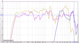
I'll include a screen shot from Room EQ Wizard with the raw woofer (yellow) and tweeter (blue) response graphs, and with the XO (purple). Mind the scale.
To answer some questions:
Is there a reason it's pointing down? Not really. 🙂 I liked the form factor. I'll put a base on it, stood-off by about the distance I was testing with, which will prevent anything from being able to poke the cone or squish the sub's surround, so that's a nice perk. But yeah, mostly it was: I think it would be fun to build a downward-firing sub.
2 subs / top: Yep, 2:1 will be possible, or 1:1, or 8:1, or whatever. The plate's XLR inputs are paralleled to the RJ45 input jack. The RJ45 output jack is switchable from pass-through (as in, parallel with the input) or a balanced output of the internal mix, post-gain, pre-EQ. The idea is to use the RCA and XLR/TRS inputs, equalize their levels, and then transmit that mix to the next unit, which will receive it, and optionally pass it on to the next. This will allow me to daisy-chain a few of these with cheap Ethernet cable, either by physically splitting the input or buffering it. The sub has a switch to select a L / R / L+R mix. (Sub only, the stereo outputs are always L and R.) This wouldn't usually make much difference, but I can abuse this to send two different audio streams down the same cable and pick one or the other. Why? I dunno yet, but it sounded like a potentially useful thing to do.
Phase: WinISD (the box modeler) says they're within 40 deg, but my measurements show more like 20 deg. I'm not sure either is totally accurate. I think I will need to re-test once my real boxes are done. Too many variables in all the prototype stages and measurements.
I had to add a Zobel network to the woofer to give the filter something to work off of, because the inductance of the woofer was starting to climb to infinity. Once that was fixed, I pushed the nastiness down as far as I could, used the nosedive at 1.8k as part of the filter, and tried to tame the slight peak right before it by sliding component values around until I got the best compromise. I would've liked to avoid that entirely, but that would've meant crossing over at 1k, which wasn't going to happen with that tweeter. I'm honestly not sure whether to be proud of the final XO, or ashamed. haha
The horn is kind of nasty by itself. You get a hump centered around 4.5k, a trough, then another hump at 12k, then it crashes. (Although the latter might be an artefact of using a class D amp -- I'm curious if that's still the case when I put a linear amp behind this. Piezo is supposed to go to the moon.) I put notch filters on both humps and got something usable.
The final XO gave me a result that is far from perfect, but overall flat from 70Hz to 14k, with a +/-3dB allowance. Some of this is going to be room stuff, diffraction, and other measurement oddities. But let's be honest. A studio monitor it is not.
I'll include a screen shot from Room EQ Wizard with the raw woofer (yellow) and tweeter (blue) response graphs, and with the XO (purple). Mind the scale.
To answer some questions:
Is there a reason it's pointing down? Not really. 🙂 I liked the form factor. I'll put a base on it, stood-off by about the distance I was testing with, which will prevent anything from being able to poke the cone or squish the sub's surround, so that's a nice perk. But yeah, mostly it was: I think it would be fun to build a downward-firing sub.
2 subs / top: Yep, 2:1 will be possible, or 1:1, or 8:1, or whatever. The plate's XLR inputs are paralleled to the RJ45 input jack. The RJ45 output jack is switchable from pass-through (as in, parallel with the input) or a balanced output of the internal mix, post-gain, pre-EQ. The idea is to use the RCA and XLR/TRS inputs, equalize their levels, and then transmit that mix to the next unit, which will receive it, and optionally pass it on to the next. This will allow me to daisy-chain a few of these with cheap Ethernet cable, either by physically splitting the input or buffering it. The sub has a switch to select a L / R / L+R mix. (Sub only, the stereo outputs are always L and R.) This wouldn't usually make much difference, but I can abuse this to send two different audio streams down the same cable and pick one or the other. Why? I dunno yet, but it sounded like a potentially useful thing to do.
Phase: WinISD (the box modeler) says they're within 40 deg, but my measurements show more like 20 deg. I'm not sure either is totally accurate. I think I will need to re-test once my real boxes are done. Too many variables in all the prototype stages and measurements.
Attachments
Getting ±33 V from 2x24 VAC sounds about right.24VAC * 1.414 -1V fwd through the bridge rectifier I chose, yields DC rails at +/- 32.936V. High line condition (10%) would net around 36.5V, so we're good there.
That sounds way too optimistic. Also note that pulling 153 W from a power supply based on a 160 VA transformer will causing the transformer to overheat. When I order transformers, the manufacturer generally asks for the expected DC output current from the power supply. They then include their own fudge factor to ensure that the transformer can handle the load.160VA might seem a bit small, but 100 + 43 + 43, with a 4.5dB crest factor yields 153W continuous.
As pointed out above the charging pulses get pretty significant and the RMS value of those pulses is quite a bit higher than the DC current drawn from the power supply. Most use a scaling factor of 1.4-1.6x, i.e., IRMS = 1.4*IDC to 1.6*IDC. Since P = E * I, you need to multiply the 153 W by 1.4-1.6 to get the transformer VA rating. So a 214 - 245 VA transformer would be needed. I'd go for 250 VA or 300 VA as those tend to be standard values. Assuming the 153 W number is correct that is.
I think you need to revisit the math, though. I give you all the necessary math to determine the power dissipated in the LM3886 here: https://neurochrome.com/pages/thermal-design. Add those numbers to the power dissipated in the load and you have the total amount of power drawn from the power supply. You can read about that here: https://neurochrome.com/pages/power-supply-design.
Yep.Thermals:
The one thing I haven't yet ran numbers on -- thermals. With 4x LM3886, there's going to be some heat.
That's pretty small, but with some airflow it'll probably work out fine. It doesn't take much airflow to drastically reduce the thermal resistance. The Noctua fans are super quiet. If you're aiming for fan cooling you can also explore CPU heat sinks.I have my eye on a 5.8 x 6" aluminum heat sink with 1" fins.
Note that a Class AB output stage has the highest power dissipation at half the maximum output power. So if you're aiming for, say, 70 W maximum, the worst case power dissipation will occur when the output power is 35 W. Your 4.5 dB crest factor will help some, but not a whole lot.
Figure 35 in the LM3886 data sheet tells you how much power is dissipated in the LM3886 for various supply voltages and output powers. Personally I would stay below 40 W dissipated
Tom
Good points, Tom. Thanks. I recognize some of those figures are ... um.. "optimistic." I'm not sure yet whether they're practical. It's complicated.
A tour of the considerations I've been mulling over... (If this isn't your cup of tea, feel free to skip over it.)
If I want to design a bullet-proof amp, then I need to calculate everything under worst-case, and ensure that both the PSU and heatsink are able to cope with that. But, even the road-worn, battle-tested PA hardware I've come to trust isn't built to run all channels driven to full power, continuously. Engineering is about balancing compromises. That is an art, though, and I have a lot to learn about what fudge factors are sensible. I've been over-estimating some, while under-estimating others, and hoping the difference will come out in the wash, while also progressively trying to replace some of the guesswork with actual calculations. It's just a lot to try and take in all at once. I've learned a few things in this thread that I've had to reconsider. That's been very helpful. I'm sure there will be more.
I've had the datasheet open to the power dissipation curves for a couple weeks now, because this is the part I haven't really finished my homework on. There are SO MANY variables here, that I'm more than likely going to either overshoot or undershoot what I actually need.
I know that the peak dissipation occurs at ~30W, given my rail voltage of +/-33. A class A/B amp is a little bit like a linear regulator, in that as power delivered goes up, power dissipated goes down, because less excess energy is burnt off as heat. But, more energy is being delivered to the load, so the net power consumed from the supply remains somewhat close to constant starting at ~15W output power. OK, so that's going be pretty relevant for the sub amps (the two parallel ICs operating, essentially as +/33V into 8R), since they're going to be driven to that level fairly regularly. It'll probably be a little bit on the high side for the tops.
There's a little bit of relief in that, given a 1V RMS signal in the preamp (which represents full-scale), the crossover is going to divvy that up between the sub and tops, so if the sub is running harder, the tops will be running proportionately lighter, and vice versa. They can't BOTH be at full volume unless the tops are running full-range. That is a technical possibility, since I have a selector switch to allow that, but it won't be common. So this is a decision point where I have to pick whether to optimize the PSU and cooling to enable full power to four channels, or two. Hm..
I picked a crest factor of 4.5dB because I knew I hadn't accounted for some significant things, like dissipation. I joke about the loudness wars, but 4.5dB crest factor is pretty ridiculous even still. I really have no intention to design for a test-bench. I don't need to play sine waves at full power, indefinitely. The cost and size trade-off is not worth it to me. The question is, what DO I want to design for?
So that's where I'm at. I know I still have work to do here. I'm going ahead with the woodwork and such, because the garage is a lot less comfortable to work in when the temperatures outside get below freezing, and I've proven the enclosure design to my satisfaction. I've kind of boxed myself in to an amp cavity that is 8 x 13.5 x 3", with a cutout (accounting for screw holes) that is 5 x 10". I'm hoping that's enough. I think it should be, and one way or another, it'll have to be.
The electronics are a WIP, and it is totally possible that I am trying to shoe-horn too much amp into too little space, and need to change course, bite the bullet, and start trying to wrap my head around Class D. I'm sure I've made it fairly obvious that my analog electronics skills are not the stuff of legend, so I'm trying to keep things simple. But, simple may not pan out. Luckily, because I have to accommodate both space and parts orientation, the amp and PSU PCBs are going to be separate, so effort spent on the preamp section is not wasted if I have to change topologies, and I can change the PSU or amp PCBs independently. This means I have some leeway to experiment, and if I don't choose my compromises correctly, I won't have to start over from scratch.
Just wanted to shed some light on this. It's part proof of concept, part experiment. I'm trying to apply proper design, build a spreadsheet with the actual calculations, and so on. I just have to figure out how much headroom I can actually afford to give up, and that's an ongoing discovery process.
Really? I only count three:I've had the datasheet open to the power dissipation curves for a couple weeks now, because this is the part I haven't really finished my homework on. There are SO MANY variables here, that I'm more than likely going to either overshoot or undershoot what I actually need.
Power dissipated in a Class AB output stage:
That's from: https://neurochrome.com/pages/thermal-design
In the equation for the power supplied by the power supply I do include the bias current, but you can ignore that for simplicity:
Still only three variables (and some constants). That's from here: https://neurochrome.com/pages/power-supply-design
Really? So the amp delivers more power to the load but somehow the power it draws from the power supply remains constant from ~15 W output power. Fascinating. Where do you suggest the power that's delivered to the load comes from?But, more energy is being delivered to the load, so the net power consumed from the supply remains somewhat close to constant starting at ~15W output power.
You should recognize these figures from the data sheet:
Let's take an example: ±30 V supply rails, 4 Ω load -> Max output power: 80 W. Power dissipated in the amp in that condition: 38 W. It then follows that the power supply delivers: 80+38 = 118 W. For 40 W output it looks more like 46 W dissipated in the LM3886 plus the 40 W delivered to the load, so 86 W pulled from the power supply.
Another example: 8 Ω, ±35 V rails. At max output power (65 W) the LM3886 dissipates 26 W. So the power delivered by the power supply is 65+26 = 91 W. At 10 W output power the power dissipated in the LM3886 is 28 W resulting in 10+28 = 38 W drawn from the power supply.
I read the dissipation numbers and max output power from the graphs, so don't expect 200% agreement if you choose to work through the math.
I agree that 4.5 dB is pretty ridiculous. Pro audio tends to use 10 dB. I use 14 dB. The 14 dB came from a survey by Sound-on-Sound where they analyzed 2500+ tracks. You can find a link to it on the Thermal Design page: https://neurochrome.com/pages/thermal-design#ThermalDesignExample2I picked a crest factor of 4.5dB because I knew I hadn't accounted for some significant things, like dissipation. I joke about the loudness wars, but 4.5dB crest factor is pretty ridiculous even still.
Tom
Really? I only count three:
Power dissipated in a Class AB output stage
Different kind of variables. ;-) I don't mean the factors you plug in to the formula, I mean the ratio of peak to average level, how you even define "average", the likelihood that the sub and mains amps are going to be contributing peak dissipation at the same time. Etc. etc.
It's not that hard to calculate the dissipation for one specific condition. It's considerably more complex to calculate the heat accumulated over time, based on some assumption about what window of time you're averaging, and what the average for that window is going to look like for various source material.
Really? So the amp delivers more power to the load but somehow the power it draws from the power supply remains constant from ~15 W output power. Fascinating. Where do you suggest the power that's delivered to the load comes from?
Alright, snarky. No. The ratio of power consumed by the load and power consumed as waste heat changes more in favor of the load as output power goes up. That's all I'm saying. Look at the dissipation charts. The downward hump toward the right? That's what I'm talking about.
I turned the 8R @ +/-35V graph into a table of values. It looks like this:
Code:
Out  Dis  Tot
  0    0    0
 10   28   38
 20   32   52
 30   33   63
 40   32   72
 50   30   80
 60   28   88
So yeah, not really, as I said, "somewhat constant" .. that was a gross and careless exaggeration. I'm trying to frame this intuitively, because that's how I better grasp concepts. I know that drives you numbers people nuts. Looking at the actual values, I would've been better off picturing that as "the dissipation stays somewhat constant." (I can see you furiously typing that it's a 5W delta, but really.. what's 5W between friends? ;-) )
The point I was making is this: Following the slope of output power vs. input power, from 30W to 60W you double the output, but your input power only goes up 25W -- less than 1W of additional input power consumed per 1W of additional output power. If we could keep going to the right, it would end up trending almost (... almost ...) entirely to Pout = Pin, but we would have to hit the transistors' saturation point, and that wouldn't be very useful.
Anyway.
I agree that 4.5 dB is pretty ridiculous. Pro audio tends to use 10 dB. I use 14 dB.
10dB is probably reasonable. The DR of lots of music now isn't anything close to 14dB, sadly. I like to download stems and multitracks from sites that cater to mixing and production, then do my own remixes just for fun. I just can't stand to listen to stuff that's too compressed. It totally ruins the song for me, and I can't enjoy it anymore. Getting to mix the same modern pop track to more like 12 or 14dB DR is transformative. I love it. I wish downloadable multitracks were a thing. I would gladly give up 24/96 downloads in exchange.
I'm off track again. Sorry. So, as I figure some of this stuff out, and make some decisions (like, on whether to give myself headroom to run 3 channels at full power), I'll substitute those placeholders with more reasonable figures and accurate calculations that aren't (presumably) making up for previous guesses.
I could've summed all this up by saying: Yep, some of that math is overly simplistic and is being replaced, slowly, with more accurate math. I just don't have my head around all the relevant factors yet, so there are a lot of "close enough for now (I hope)" values.
Arh... You did say:
It's the power that's dissipated in the LM3886 that remains somewhat close to constant.
You're right that you're unlikely to be able to determine an exact analytical solution. But you could certainly compute the average power dissipated in the LM3886 from the rail voltage, the load impedance, and the data in a .wav file for your music of choice. It wouldn't be hard to write a script to do the job. But it would be complete and total overkill.
In reality many of the variables are only known with one or maybe two significant digits. The thermal resistance of the heat sink, for example, is typically specified for a temperature rise of 70-75 ºC. You probably don't want to run it that hot. You probably want to stay below 60-65 ºC, so you only have 35-40 ºC of temperature rise to work with. That makes the heat sink less efficient, so you need to apply a correction factor. There went your precision...
That's why engineers make assumptions. It makes solving the math possible. I would make these assumptions to start:
Don't forget to multiply the power consumed from the power supply by that 1.4-1.6 factor (see - only one known significant digit!) that I mentioned previously to get the VA rating of the transformer.
Some would rightfully argue that this approach results in a design that's too conservative. They'd want to skimp more, especially on the heat sink. I've based my designs on this approach and find that when I run the amp with a 32-tone test signal with a CF of 10 dB the heat sinks reach 60-65 ºC – just as I designed for – after about an hour.
Best of luck.
Tom
That's not true even by approximation. From the data in your table you'll notice that the power consumed from the power supply about doubles from Pout=15 W to Pout=60 W.the net power consumed from the supply remains somewhat close to constant starting at ~15W output power.
It's the power that's dissipated in the LM3886 that remains somewhat close to constant.
You're right that you're unlikely to be able to determine an exact analytical solution. But you could certainly compute the average power dissipated in the LM3886 from the rail voltage, the load impedance, and the data in a .wav file for your music of choice. It wouldn't be hard to write a script to do the job. But it would be complete and total overkill.
In reality many of the variables are only known with one or maybe two significant digits. The thermal resistance of the heat sink, for example, is typically specified for a temperature rise of 70-75 ºC. You probably don't want to run it that hot. You probably want to stay below 60-65 ºC, so you only have 35-40 ºC of temperature rise to work with. That makes the heat sink less efficient, so you need to apply a correction factor. There went your precision...
That's why engineers make assumptions. It makes solving the math possible. I would make these assumptions to start:
- The heat sink is isothermal (i.e., without hot spots).
- The ambient temperature is 25 ºC and there is free airflow along the fins of the heat sink.
- The speakers present a resistive load equal to their nominal impedance.
- The power supply voltage remains constant throughout the signal swing.
- The crest factor of music is 10 dB (or 14 dB).
- Music is played with the peaks at levels just below clipping.
Don't forget to multiply the power consumed from the power supply by that 1.4-1.6 factor (see - only one known significant digit!) that I mentioned previously to get the VA rating of the transformer.
Some would rightfully argue that this approach results in a design that's too conservative. They'd want to skimp more, especially on the heat sink. I've based my designs on this approach and find that when I run the amp with a 32-tone test signal with a CF of 10 dB the heat sinks reach 60-65 ºC – just as I designed for – after about an hour.
Best of luck.
Tom
From a purely experiential POV, the peak power dissipation point doesn't actually help at all in practice - meaning that you never actually get the benefit of it falling above that point. There are a few reasons for this, one of which is obviously CF in that as you move towards clipping, so the majority of the signal goes into that peak dissipation range. But also all the temperature gradients are shallower, including in your use case, the one from heatsink to ambient, so there's less heat flow outwards. The experience we all have is that the more you turn an amp up, the hotter it gets. I don't know of anyone who has actually thought "Well, if I turn it up a bit more then the temperature should go down.". And if they've tried that in practice, I'll wager that it has been a disaster. 🙂🙂
Forced air, then, changes the picture completely. But having your fan on full from the beginning is a BAD idea. Amps sound best in cases and there are some good reasons for this. The betas of the transistors change with temperature (and one of the main problems with chip amps are the thermal waves across the more sensitive parts of the circuit - and thermal memory is a topic by itself in amp design) but so do the values of the resistors change with temperature. One of the reasons that amps like casework is because it provides a warm and stable ambient environment. When an amp is cold there are wilder swings in the temperature of the resistors because they heat up instantly with the power dissipated and then discharge that heat quickly into a low temperature ambient setting. This can directly affect gains - and simply matching the TCR of the feedback resistors does not do the trick of eliminating this. There are ways of matching it but in general they are always out by the factor of your gain, even with the same TCR. (Incidentally, this is a measureable source of distortion even in pre-amps, so it's not up for debate.) Obviously ultra low TCR helps here but then you are getting into the realm of specialist hi fi and it gets expensive. OTOH, definitely don't go for a standard white ceramic resistor with a TCR of 300ppm just because you foresee it dissipating power. (These don't even sound good in speakers.) My recommendation would be to have a tickover base airflow of 5cm/s - which you should be able to measure easily - so as to hand you some additional heat capacity and then, above a threshold, have it come on linearly above that. You can vary the threshold and the gradient of your speed rise with experience.
Re. your 1V being a bottleneck, I wonder firstly whether it actually is and then whether or not it's desirable to have one. As you know, my recommendation is to do it actively throughout, but the split between sub and top is active anyway. The reasons to have it active between mid and treble are numerous but one is that any clipping in the mid bass won't come out of the tweeter section. In both cases there's a potential for an increase in dynamic range of up to 6dB which I wouldn't throw away, especially in an under-powered system. (The full 6dB is obviously in pretty special musical circumstances and your choice of crossover point will determine how likely you are to get a chunk of it, but some of it is going to be there and it represents what would otherwise be a huge increase in rail voltage.) I'll also add that there are generally unknown pitfalls in passive tweeter sections that, for a set level of expertise, make the active implementation far more likely to be successful than its passive equivalent. Your 1V peak limit potentially throws these advantages away. Assuming there's no gain in the crossover sections (and you can do these without gain unless you want an equal value S-K) then you've got your signal clipping, a) before it gets to the x-o, so God knows what each of the filter sections are going to do to that, and b) without knowing whether that signal would have clipped in any of the amplifiers. Splitting the amplifiers into judiciously chosen frequency bands gives you a chance of effectively lowering your crest factor and while I'm not saying it will get you over the rising section of power dissipation (I'd want to model that with different music types to give any sort authoritative answer) it might well help. (Or it might not, and just put everything higher up the curve.) But you are still throwing away potential dynamic range and potential power output. And since you say you don't like compression in recorded music, while this will not undo it, it at least will be doing the utmost to avoid adding the audio amplifier version of it - which is all the peaks going into clipping (and efforts being made in amplifiers to make that as benign sounding as possible) while the body of the music moves up in level. Finally, it is worth noting that if you find that in this scenario you are above the power capability of the 4" mid-bass - which I'm assuming is the weakest point - then you can lower the rail voltages for the top two amps and ease up on the heating problem too. I shouldn't think that'll happen with a 1" voice coil and a signal already at half power at 130Hz but an easy way to drop the rails would be with some JLH style LM317/337 power transistor assisted regulators. The LM317 is really not that great as a part these days (though I do still find myself using it from time to time) but this sort of regulator is so easy to knock up that the temptation is overwhelming. Personally I do them with a CFP rather than a single power transitor but there are some arguments that may not be quite as good as it at first appears, so take your pick. There are anyway some nice wide bandwidth, highish beta power transistors available these days, so you don't have to beef up the shortcomings of one of the old lumbering giants.
Re. your 1V being a bottleneck, I wonder firstly whether it actually is and then whether or not it's desirable to have one.
1V at the line level stage isn't the bottleneck. For the preamp, I've tentatively chosen +/-12V rails (worth revisiting at some point, but I think it'll be adequate), so there's little danger of running into a limitation there. The limitation is that, with 1V in the internal line-level circuitry, and a gain of 19, the power amp will go into clipping. (Well, assuming that channel gets all or the majority of the signal swing, anyway.)
As you know, my recommendation is to do it actively throughout, but the split between sub and top is active anyway.
Yup, I hear you, and I agree. But, it's not feasible for this project. I mix and match equipment too much to dedicate these subs as 3-way amplifiers for those specific tops, and only those tops. And, likewise in reverse -- those tops are then bi-amplified by those subs, and only those subs. It would be a superior solution when they're combined, but it would eliminate any other pairing possibilities. And given that these need to sound "good" but not "flawless," I don't think it's really worth the trade-off. If they were meant to be inseparable, or if fidelity were the principle goal, then I would probably make the tops active and feed them with a high-passed pre out. Maybe even put a DC jack on the sub to provide power. 🙂
Assuming there's no gain in the crossover sections (and you can do these without gain unless you want an equal value S-K) then you've got your signal clipping, a) before it gets to the x-o, so God knows what each of the filter sections are going to do to that, and b) without knowing whether that signal would have clipped in any of the amplifiers.
There is no gain in the active XOs, but there is gain at several points before them, and the sub has a +/- level trim after. I have dropped a tap at each point where there is gain, so I can feed them into a comparator and have clip detection at each stage, which would all combine to a single clip indicator LED. It's technically possible for the op-amps to clip in several places, but anything that gets the signal that hot would almost definitely be pegging the amps anyway, unless the gain staging was all out of sorts. There's a volume control before the XOs, post input and EQ sections, so you CAN, technically, drive the processing chain into the red and limit the volume before the amp. Testing for clip at each stage would alert the operator (namely, me) of that. That would be nice, and I'm going to try and do that. But I'll have to finish the design and see if the parts and board space are worth it. The other clip indicator is free: It'll sound like crap if it's too loud anywhere, and I'll just have to turn down one stage at a time until I find the culprit.
Finally, it is worth noting that if you find that in this scenario you are above the power capability of the 4" mid-bass - which I'm assuming is the weakest point - then you can lower the rail voltages for the top two amps and ease up on the heating problem too.
In terms of the drivers' thermal power handling, yes, the mid-woof is technically the weak link... but as it turns out, not by much, and depending on the source material, maybe not at all.
I'll most likely clip the sub first, and then which channel hits thermal overload first depends on the spectral density of each channel. The drivers happen to be fairly well matched in that regard, according to the SPL graphs in WinISD. 100W at the sub is within 0.5dB of 43W into the tops. That's peak power, where the sub amp will begin clipping, but the top amps will still have a few volts headroom and the 4" driver is still within Xmax. 3dB down would put the sub at 50W (thermal limit), and 22W on the tops (below their 35W thermal limit).
Bass-heavy music might require that I link a second (or third...) sub, if I need the SPL. If I've got somebody on a mic doing announcements, I'll be leaning on my signal processing rack to compress and limit. But I always do anyway.

"I mix and match equipment too much to dedicate these subs as 3-way amplifiers for those specific tops, and only those tops. And, likewise in reverse -- those tops are then bi-amplified by those subs, and only those subs."
Wouldn't plug-in crossover sections be the answer here? Harwin make some superb little pins which are a joy even just to look at - with some nice little shorting hooks too which look gorgeous also. Like everything from Harwin, they aren't half expensive, though! I don't know who makes the Naim plugs/sockets but they seem to work well too. But even those rows of standard 5.08mm spaced pins will do. AFAICS they all end up with around 3 milliohms of resistance so I guess the thickness of plating, hopefully indicative of lifespan, is probably the key criterion.
Removeable daughter boards would be so much easier than having to unwire the amp every time and be so much more flexible when it comes to modifications and upgrades. You could even leave room for additional sections, though it's Sod's Law that what you want to do in the future won't have been accomodated, but it might make the mods a bit less of a rat's nest. This way all your subsequent satellites can be fully active. Ultimately active crossovers are far easier than passive and are more likely to yield pleasing results, though it's hard to get this fact across to most people because of the "terror" factor. Incidentally, another interim solution is to have an equalisation part (if that's needed - which here it is, I think) and a generic, theoretical filter part. Then you can bypass the equalisation if you want to try another, flatter driver. Passively, you would have to design a whole new section to take into acount that driver's impedance which is far more laborious.
- Home
- Amplifiers
- Chip Amps
- I don't understand LM3886 rail calculations - pls help