I typed "peak rms peak-to-peak" into a Google image search and found this. Looks useful...

Tom
Tom

I have no idea what you're talking about. What specs am I disregarding?Your choice of course.
You can also choose to disregard LM3886 specs.
Ok.
The confusion is mostly talking in circles. I've understood my initial error since post #9. The rest of this has been a long game of "Who's On First?" and reiterating the same question, with helpful responses like "RMS is RMS. Draw a picture. Don't overthink it. Just follow the formula. Who cares if you don't understand it, it'll just magically work!"I don't know why so much confusion. Everything is on the LM3886 datasheet, also you can read articles of neurochrome website. Everything is there. I made my first lm3886 without any problem by following everything stated above. I did some modifications & choose every part convenient to my purchased pcb's. The amplifier running well past 1 year or so without any oscillations or such thing. Traditionally chipamps are quite straightforward, you just need to implement it properly. Anyway if you want to play with oscilloscope for vanishing THD or last drop of so called "RMS" you need to know the math well.
Best Regards
THAT.... is exactly what I was looking for. I just didn't know the question to ask. I had the formulas to convert between RMS and peak, and that made perfect sense. The reason to use RMS made sense (i.e., AC cannot be represented with a single measurement, it needs to be windowed.) All I knew is that my calculations didn't agree with the datasheet calculations, and I didn't know why.I typed "peak rms peak-to-peak" into a Google image search and found this. Looks useful...
View attachment 1215270
Tom
If you boil it down to one thing, I think my main point of confusion is that I wasn't sure whether I could trust that any time the word "peak" was used, it was only to describe the potential between 0V and the top of one half cycle of the waveform. It seemed possible that "peak" was being used interchangeably with "peak-to-peak" as a sloppy shorthand, and I couldn't find anything that gave me confidence whether that's was actually the case. Some material made clear distinctions, others only used "peak" and I couldn't tell for 100% sure.
This got lost in the shuffle. It would've told me exactly what I was getting wrong, had this been on page one, though. Thank you. I appreciate it.There is a difference between peak and peak to peak you are maybe missing. Take Voltmeter RMS and multiply by 2.83 for peak to peak. Divide by two and this gives you one rail the other is the opposite polarity. For 100 Watts into 8 Ohms 28 Volts RMS times 2.83 = 79.24 divide by 2 for 39.6. With no loss you need + and - 40 Volt rails. Of course there will be a couple volt loss.
You said so many times in this thread :I have no idea what you're talking about. What specs am I disregarding?
Well beyond LM3886 recommended spec.or max +/-39V if I use the 15% regulation and 10% high line figures.
No way you can feed it from raw +/-39V rails into a speaker load and make it survive.
LM3886 can put out 20V RMS at most so again you are disregarding its specs.based on reaching Xlim @ 22VAC
Maybe they all have a point.But the data sheet, and lots of forum posts about 4R loads all seem to be insisting that I should have more, just for ~40-60W.
You won´t.If I'm measuring across the output terminals of my power amp, and I get 22VAC,
Hint, it´s beyond LM3886 specs.
But you are NOT getting 22V RMSIs the 22VAC reading I'm getting
Not from LM3886.
You must accept the datasheet spec ..... or else.the fact that there's up to a 2x discrepancy in what I intuit the rails need to be, and what the data sheet says they need to be.
You are getting into trouble by NOT following what the datasheet specs say.I could just "do what the data sheet says to do" and it would most likely be fine. But then, if it IS wrong, I have just backed myself into a thermal corner that I need to get out of. Not good.
But all of this boils down to your statement:
Eeeeehhhh??? WTF?Now, regarding advice that amounts to "just do what it says" and "here are some working designs, use those" .... ehhh, thanks, but no. 🙂
If there is something you can NOT do is disregard datasheet specs.
Oh well, no good deed goes unpunished 😉
Just try to follow this for approx maximum output power into desired load--
+/-28Vdc(Vpeak, +/-5%) for 4R load
+/-32Vdc( ,, ,,) for 6R load
+/-35Vdc( ,, ,,) for 8R load
**All supply voltages stated above are after rectification & large filter capacitors (Lm3886 Standby/quiescent state). I think this will help you understand things a bit. Anyway I need some sleep now 🥱
+/-28Vdc(Vpeak, +/-5%) for 4R load
+/-32Vdc( ,, ,,) for 6R load
+/-35Vdc( ,, ,,) for 8R load
**All supply voltages stated above are after rectification & large filter capacitors (Lm3886 Standby/quiescent state). I think this will help you understand things a bit. Anyway I need some sleep now 🥱
You're misinterpreting a lot, here. Let me clarify:You said so many times in this thread :
The "max 39V if I use 15% regulation and 10% high line figures" was the raw output of the formulas to calculate DC rail voltages. Not a design plan. It's also below the abs. max rating of +/-42V. And before anyone jumps in with "but you don't ever want to run it to max" -- this is already the maximum DC rail voltage AFTER accounting for high line conditions. So it's 3V shy of max, in worst-case conditions. But that's all irrelevant, because it's not the plan, it was an example of the calculated result of the formulas, and that's all.
About "22V RMS" -- I specifically stated this was a test that I ran using my Crown XLS202 power amp, to determine the maximum amount of voltage I could feed into the sub, in its box, with a 60Hz sine, before it hit physical limits. This informed my design goal, which is max 100W, which at 3.6R, is ~19V. I want to be able to hit this target (e.g., a kick drum), understanding that I can't play dubstep with 100W continuous, or the driver probably won't live a very long and happy life.
Now, regarding "you MUST accept the datasheet spec" and "if there is something you can NOT do is disregard datasheet specs." You're under the incorrect impression that I'm doubting the accuracy of the calculations in the datasheet. I am not. I never was.
I initially came up with a very different number, and that stopped me in my tracks. It was clear I was doing something wrong, and I wanted to find out what. I could have just gone ahead with the (datasheet) numbers as-is and would have probably designed a perfectly functional amp. But when my numbers don't match the datasheet, I want to know why, because it means there's a fundamental flaw in my understanding, and I would really prefer to resolve that. It was purely a quest for knowledge.
That is why I'm not interested in the offers for "just use these figures and save yourself the trouble." No. I could just as easily buy an off-the-shelf plate amp and be done with it. That's not the point here, because then I would still be mistaken in how AC VRMS are measured. It wouldn't have fixed a misunderstanding I've had for who even knows how long, and got from who knows where.
Thanks, but:Just try to follow this for approx maximum output power into desired load--
+/-28Vdc(Vpeak, +/-5%) for 4R load
+/-32Vdc( ,, ,,) for 6R load
+/-35Vdc( ,, ,,) for 8R load
**All supply voltages stated above are after rectification & large filter capacitors (Lm3886 Standby/quiescent state). I think this will help you understand things a bit. Anyway I need some sleep now 🥱
1) I've said this many times already, so forgive the repetition -- I've already found out what I was having trouble understanding in post #9.
2) If I hadn't, this wouldn't actually clarify what I was goofed up on. It's the answer without understanding how to get the answer, which defeats the reason for starting the thread.
3) If I just used the 4R load figure, +/-28VDC wouldn't be enough to reach my design goal.
4) The subwoofer will be powered by 2x LM3886 in parallel, so technically I could use the 8R figure, since 1x LM3886 @ 4R is equivalent to 2x LM3886 @ 8R, but if I were just looking for a cookie-cutter answer, I'm not sure that would've been obvious.
I appreciate it anyway.
Many arguments go in circles around the LM3886 power supply voltage. The spec is a bit confusing as the chip will be able to tolerate a higher supply voltage without signal applied than it can with signal applied. Most of us use the LM3886 with signal applied (otherwise what's the point?!), hence, the maximum of ±42 V applies.
I would allow for at least ±10% mains variation, so unless you have a regulated supply you're now down to ±38 V. You then add that a typical LM3886 can't actually deliver more than 7 A of output current and that its drop-out (or saturation) voltage increases dramatically at heavier load and you end up with the recommended target voltages mentioned by @NanoFarad. I write about it at great length here as well: https://neurochrome.com/pages/output-power
Tom
Exactly the chip can handle more voltage
than its feasible thermal limit.
Been well known not to expect more than 40 watts
as stated in datasheet.
And agree with other comments.
Only so many off the shelf transformers and common
voltages. So after DC rectification pretty common values are reached
with common transformers. Depending on VA rating.
Typically with class A/B just double the VA for expected power
and expect the usual higher voltage at idle.
Then slight sag when powered.
Easy and simple.
Wire up transformer and go.
Parallel 80 watts use 160 to 250 VA transformer
stereo use 330 to 500 VA
Real world power use , always lower.
Unless a very low efficiency sub.
And chip amps are out of the picture
for subs needing 100 watts or more for
real world listening levels.
Real world that is
Not mystical overblown levels.
Last edited:
It's not what I would recommend, but I'm running a 3886 off ±44 V at the reservoir caps into nominal 4R speakers and have had no problems whatever over quite a number of years. There are a few probably mitigating factors like the speaker load being almost perfectly resistive, apart from the LF resonance, and even there it's a sealed cabinet so the phase shifts are small - actually inside ±36 degrees. Nor is it a heavy bass unit likely to produce large back EMFs.Many arguments go in circles around the LM3886 power supply voltage. The spec is a bit confusing as the chip will be able to tolerate a higher supply voltage without signal applied than it can with signal applied. Most of us use the LM3886 with signal applied (otherwise what's the point?!), hence, the maximum of ±42 V applies.
It's happenstance that I arrived at this arrangement (and wouldn't have set out to do it) but it's not only surprising what the 3886 will take, but also that this is one of the best sounding of the chip amps I've built. I've been as low as +40VDC (regulated down from ~48V) on a single supply amp, so equivalent to ±20V, to the more usual ±36 V supply and this one easily tops the lot, with a lot less work put in, too. It does have a careful layout though, and has a small C across the inputs. And, FWIW, 220uF at the supply pins since someone else mentioned it. It's actually good enough to deserve a regulated supply (and with it an easier life) but I just haven't got round to it. My next project with it may well be to use it as a semi-driver for a discrete o/p stage and see what happens when it's relieved of the thermal waves across it.
They are surprisingly robust little things and my experience is you are more likely to destroy them by changing speakers with it on (without an output inductor) than you are by cranking up the volume. I would have thought two of them in parallel with up to ±40V rails would be just the ticket for a reasonably beefy 4 ohm (probably 3.x DCR) sub. The problem with subs is that once you've put one in, you then want another. And then more and more, and more. 🙂
Would that be true of the TDA729x chips, where you can have a slave in parallel and where, from memory, I think you can have ±50V? Or you can parallel them up with some power transistors - though, please God, not the way that Linn did it in their amps. I've never actually tried them as I haven't been that impressed with the specs or the quality of the documentation. But that extra voltage headroom could be very tempting.And chip amps are out of the picture
for subs needing 100 watts or more for
real world listening levels.
Maybe you got lucky. The data sheet clearly states 84 V (±42 V) as the absolute maximum with signal applied.It's not what I would recommend, but I'm running a 3886 off ±44 V at the reservoir caps into nominal 4R speakers and have had no problems whatever over quite a number of years.
Also note that the performance with 4 Ω load at supply voltages above ±32 V is degraded. The SPiKe protection kicks in and the amp starts to distort. I doubt you're getting much more than 20 W out of it. Had you stayed at the recommended ±30 V you'd have gotten 70 W before clipping...
Tom
Interesting. I will put it on my AP next time I have the amp out. But it's not what I remember. Basically it did a bit better than the spec sheet - not quite twice as well IIRC - due to it having half the gain and therefore twice the bandwidth. As for 20W, it melted all the solder on my array of 25W resistors which were bonded to a 15mm slab of aluminium. That actually brought those measurements to an end so I never did get to measure its full power. In fact I can't remember what load I used; I may have compromised on 4R7. As for what it achieved, I remember telling Roy George that the top end was between 0.01 and 0.02% (which, looking now, isn't actually that much better than the datasheet).
I tend to like playing things pretty loud from time to time, and if the reputation of the SPiKe protection is as horrible as people say, then I'd like to think I'd have heard it. I do have a limit on what the drivers can take so maybe I've backed away from really thrashing it. It's not as absolutely effortless or as difficult to fault as Tim de P's A370 (which was just a cracking amplifier/room heater) but it's really not at all bad considering the execution is pretty vanilla. And I reckon I could get more out of it quite easily, not least because it was going to be two in parallel, but I only built up one side for testing, and it was going to have a rather sophisticated regulator on each channel as well; more sophisticated than the Naim DR by some margin.
Still, I'll let you know what it does produce when that moment makes itself available. It's not the most important bit of amplifier work I have at the moment but it (and its single supply cousin) is an ongoing project.
Many arguments go in circles around the LM3886 power supply voltage. The spec is a bit confusing as the chip will be able to tolerate a higher supply voltage without signal applied than it can with signal applied. Most of us use the LM3886 with signal applied (otherwise what's the point?!), hence, the maximum of ±42 V applies.
I would allow for at least ±10% mains variation, so unless you have a regulated supply you're now down to ±38 V. You then add that a typical LM3886 can't actually deliver more than 7 A of output current and that its drop-out (or saturation) voltage increases dramatically at heavier load and you end up with the recommended target voltages mentioned by @NanoFarad. I write about it at great length here as well: https://neurochrome.com/pages/output-power
The bit about tolerating higher voltages w/ no signal makes sense, because that's what a transformer's power output is likely to do, right? Loaded, it will sag a bit. Unloaded, it will float back up to nominal.
I built a Google Docs sheet with the calculations so I could fiddle with the numbers, and keep notes as I start finding variables to nail down. Here's what I have so far:
First, a little more about the project, for anyone who is interested. (Feel free to skip this paragraph otherwise.)
The system will be a powered sub with 2-ch output for powering a set of mains as well. I run sound for a few events, just for fun, or bands I'm in, or events for family and friends -- that sort of thing. My main PA setup is a pair of Yamaha Club V 12" + 1" compression horn at ~200W/ch., and I have a few subs to pick from, with a pair of Crown XLS802s to power them. It's a nice setup, but it's often too much firepower. I needed something better suited to indoor use, and often also would prefer less sound in more places than more sound in one place. This design is intended to be a linkable (balanced audio over UTP cable) micro-PA better suited for social gatherings or background music at outdoor events that tend to sprawl away from a central location. I'm building 8x of the subs, and have the parts for 12x of the tops, but the cutsheets I made for the birch ply sheets I got yielded 16 so I'm building them all. It's a bit of an experiment, but I've wanted something like this for a while, so I'm going to give it a shot and see what happens.
OK, now the engineering part of it:
The sub's target is 19V / 100W max. The plate will have an RCA input with -10dBv sensitivity, and balanced combo TRS/XLR with +4dBu sensitivity. Both will be normalized to 1V nominal internally. There are level trims for both, a 3-band EQ (LS, mid cut, HS), and sub level control, all with +/-6dB range, plus a volume control (0dB to -inf.), so there's a potential for higher level, but the amp's gain is set at 19, so it will clip at more than 1V.
The stereo out will be configured for the same gain, because I don't want to lock this into a specific pair of tops, but I figure a reasonable target will be 16V / 43W max / ch. into a nominal 5.9R, for the tops I've designed. Those use the Dayton Audio DS115-8, 4" mid/woof. It's rated for 35W, but WinISD suggest the excursion limit (with a HPF @ 85Hz, 2nd order) happens to be around the 43W mark, so it's a good match. The +/-6dB level knob on the sub channel will allow matching efficiency levels and to taste.
Output:
Sub - 3.6R @ 19V = 5.28A, 100W. Signal will be +/- 26.87V peak.
Tops - 5.9R @ 16V = 2.71A/ch., 43W. Signal will be +/- 22.62V peak.
Transformer:
I chose 24-0-24, rated for 160VA, with 8% regulation at full load.
24VAC * 1.414 -1V fwd through the bridge rectifier I chose, yields DC rails at +/- 32.936V. High line condition (10%) would net around 36.5V, so we're good there.
160VA might seem a bit small, but 100 + 43 + 43, with a 4.5dB crest factor yields 153W continuous. And at that point, I'm already beyond the long-term limits of the drivers. So, real-world, 160VA should be OK... (But please correct me if I'm wrong.) I did some fairly basic simulation, and it seems like 20,000uF on the +/- rails should suffice well enough. It'll start to droop at full load, but that's probably for the best.
Thermals:
The one thing I haven't yet ran numbers on -- thermals. With 4x LM3886, there's going to be some heat. I have my eye on a 5.8 x 6" aluminum heat sink with 1" fins. It might be borderline, so I'm planning to put it in the inside (isolated) amp cavity of the sub, and run a small 12v blower just to generate a slight breeze, from vent holes in the bottom of amp plate, up through the fins, and out vent holes in the top.
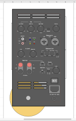
Attached: Mockup of the plate amp panel.
Also attached: The prototypes, powered from a Dayton class D desktop amp. I was testing the passive XO for the top here. The laptop had complimentary LR24 filters applied to the L and R channels, and a bit of trim to match levels. The top was a whimsical design, intended to be a mini-me clone of the Yamaha Club V. I've been calling it Club II, but I'm tempted to call it the Club IV, given the 4" mid-woof.
Attachments

Sorry, but that's not how you calculate the VA rating you need. The charging of the reservoir caps happens in short duration, high current spikes and the larger your reservoir caps, the larger those will be. Yes, it does theoretically have time to cool in between, but it doesn't average out the same. The power is proportional to I squared and if you are skilled with LTspice or some other Spice simulator you can work out what this is going to be. How much margin you are offered on your VA rating will depend on your manufacturer but of course they don't offer as much as they used to as the rating is what justifies the money. Some of them will be thinking like you, having just come out of business school, and be totally unaware of how transformers are used IRL. This is just the sort of analysis that I would normally charge for but, for the moment I'd guess you need to drop your caps down to perhaps 15,000uF or perhaps 2 x 6,800uF and up your VA rating to 250 or 300VA (and you may still be marginal, though touching it IRL will be a jolly good indicator). I generally use my 3886 amp with a 300VA transformer (for domestic use) though at present it is 300VA on one channel, with a 500 VA supply waiting in the wings. Also, spend what you are saving on capacitor value on a higher quality product. ESR in reservoir caps does deadly things to the waveform - and, no it doesn't, sadly, provide just a nice extra touch of damping. Even with two in parallel you probably will still be breaching the ripple current limit but that doesn't tend to matter so much, as long as it's not egregious. Again, touching them will be a good indicator and heat means a shorter life - or danger if it's too hot to touch (which should be unlikely). This is a good reason to go for 105degC caps rather than the industrial 85C. Capacitors don't have an indefinite life anyway.
Incidentally, with 15,000uF you are marginal on current inrush and may need to charge them through 5R to 10R before switching on a relay. This may be worse on a 110V supply but I'm not sufficiently au fait with the quirks of US mains to know how far you can push it. You can just about get away with it here but you might trip an occasional house. Good practice would eliminate that possibility.
Edit: If you are going to touch the transformer, do please switch it off first as I'm sure you know mains can be lethal. Or, better still, point an IR gun at it and the capacitors. That'll give you a much better idea of the temperature profile and whether there are any hot spots. Incidentally, there are regs (in the UK at least) about having any uninsulated surface be over 65C, I think. It may be 60C, but if you can't hold your hand/fingers on the heatsink continuously, it's too high. Bear in mind that the speaker too will be heating the ambient air, which is not going to help. A separate chamber and judicious internal airflow management may well be required.
Last edited:
OK, thanks, that's helpful. To address some of those concerns:
There's a seperate (isolated) chamber for the amp. I didn't want to worry about trying to seal the plate, and if you look at the attached image, it has vents anyway, so ... The heatsink will be on the inside of the amp cavity. This was more about sharp edges on things protruding from what is supposed to be a portable sub, than protecting fingers from heat sources. But it's a side bonus. That said, I really don't want to be running the internals at 60C either way, if that can be helped. Hence the plan for a bit of active cooling, since my convection efficiency is going to be awful anyway.
About the VA rating: This was one thing I wasn't sure about. The calculation only assumed Watts In would have to equal Watts Out, but, as you said, linear supplies aren't exactly ideal resistive loads, either. I didn't really know what kind of derating would apply here. I don't imagine people use mains transformers for much other than linear supplies, so is that already baked-in to the load rating? There's no mention anywhere of surge or repetitive peak loads in the datasheet, just temp constraints.
Anyway, I have options for 160VA and 250VA at the same secondary voltage. I actually bought a 250VA toroid for testing, and the mounting location will accommodate either. If I have to use the larger size, that's fine. It's an extra $15/unit, so, meh.
A soft start relay is already in the cards. Haven't started working on that yet, but it has pretty much always been the plan. I might have two, three, four of these on a circuit. That circuit might be a 2000W generator. Those things really hate it when I turn on the XLS802...
I think the caps will be OK. Due to the form factor, I'm obligated to go with banks of smaller caps, rather than a single large can. I am toying with physical layout, and space is the limiting factor, but one contender is 4x3300uF + 3x2200uF per rail. This puts me at 19800uF, give or take 20%, plus any local capacitance on the PCB, etc.
So you're basically going to go ahead and do what you were going to do anyway. Hmmm... Do you have a some small precision resistors to measure those charging spikes. Let me know when they blow up.
In honour of your touching faith in the properties of enamel, I must recommend a product I saw on Amazon a few years back. It's a mains powered electrolytic footbath. The 12V terminals are in the water and the electrolysis supposedly helps clean your feet and revitalise you. What is most exhilarating, though, is knowing that you are always just a layer or two of Chinese enamel away from death. Could anything be more exciting? I'm sure I can find the link to it if you'd like me to. 😉
In honour of your touching faith in the properties of enamel, I must recommend a product I saw on Amazon a few years back. It's a mains powered electrolytic footbath. The 12V terminals are in the water and the electrolysis supposedly helps clean your feet and revitalise you. What is most exhilarating, though, is knowing that you are always just a layer or two of Chinese enamel away from death. Could anything be more exciting? I'm sure I can find the link to it if you'd like me to. 😉
What are you even talking about?
Your points were:
1) Transformer is too small at 160VA. 250VA is a likely minimum.
I admitted the 160VA was an uneducated guess, and already bought a 250VA to test with. Hopefully that's enough, because I already designed around that possibility. Since your post, I did a little more research on this to see if there are some good rules of thumb, if the math would be accessible, or if I just need to build it and see what its limits are. More to learn, but so far 250VA seems like it might be OK.
2) Probably don't need 20mF, 15mF might be enough.
Noted. My current total is 19.8mF, and it's a work-in-progress. Whatever.
3) Watch the ESR and opt for 105C.
I usually buy low-ESR 105C caps anyway, so .. yeah, done. Given that I'm paralleling smaller caps, I should have plenty of headroom here re: ripple current. AFAICT, I'm well in the clear. Will need to stress test this some, but that's a given.
4) Inrush is potentially going to be a problem.
Agreed, and already intended to deal with this.
So, please enlighten me... what advice do you think I'm blatantly ignoring?
You guys seem to be skimming the text, making up a story on what you think it said, and holding that (often wrong) assumption against me. Then, if I dare to question it, I turn into the "newbie questioning the experts."
What the heck, guys?
- Home
- Amplifiers
- Chip Amps
- I don't understand LM3886 rail calculations - pls help