
Hi There
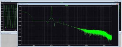
I have look at this design, and simulate it, I see it has moderate distortion with higher output.
I did do some myself, I can post it if you like, because I ask first to prevent hijacking the thread.
I did see when use a fet as driver for thout output transistor do a lot better, that is because better
matching with pream who is a very simple gain stage, I use a current mirror.
regards
... there are any number of simulation wizards ... I am humbled... 🙁
Sir, in the old-fashioned world, the proof of the pudding is in the eating.
Go, build it, and measure to your heart's content ... and share the results if you feel like it.
When you have some free time, listen to it and derive some happiness and satisfaction too ... my humble suggestion for what it is worth ...
I have set a autobias in it and go build, but it is quite different setup, the design here was with bjt did have to high distortion.
I have use mosfet in the output and jfet in input incl a current mirror. I did in past work on a allfet circlotron but that did not work out well.
These I go build, more simple and driver section included in supply voltages like you did.
regards
I have use mosfet in the output and jfet in input incl a current mirror. I did in past work on a allfet circlotron but that did not work out well.
These I go build, more simple and driver section included in supply voltages like you did.
regards
Attachments

Simulation and exploration of new alleys is all fine, but the question here is, did you build and measure the BJT version and compare that with your (built) FET version and found it superior? If so, I think your posts will be more than welcome.
Taking a simple and elegant design and saddling it with bells and whistles and belts and suspenders is totally up to you.. I am no pundit to judge that. As a layman hobbyist and I go for the direct "build and listen" path.
Big thanks for your interest in something that has remained "below the radar" for long ... 🙏
I am started building it, mosfet version who do better with distortion.
It will be setup with normal bias setup and auto bias.
I look how it sounds, I put a video of it on youtube.
vrgads
It will be setup with normal bias setup and auto bias.
I look how it sounds, I put a video of it on youtube.
vrgads
Hope Polyphaze will chip in with comments .. once he stops listening and drags himself away from his Infinitron ...
😉🙂
😉🙂
Maybe, he is free to use mine comments and ideas for it.
I have also a extra project restauration of a opel manta B. But that is a summer project.
I have also a extra project restauration of a opel manta B. But that is a summer project.
I think Polyphaze is gone no comments anymore.
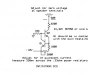
I have to say also that the schematic I did provide is quite different from the Polyphaze version,
all the ciclrotrons has a common way to design it. I like to use preamps with differential voltages driving
the circlotron output. But for simplicity mine idea or these from Polyphaze can be used.
regrads
Last edited:
I see Polyphaze has no interests anymore, I hope it is not because I did post some adjusted schematics, I had no plan to hijack it, just some
help.
Oke I have received the parts so I go try it, including autobias.
help.
Oke I have received the parts so I go try it, including autobias.
... not many active participants, probably that's why...
Do finish your build and post details here...something for all of us to look forward to ...
Do finish your build and post details here...something for all of us to look forward to ...
Well I had the parts however she did send the wrong ones, 500 ohm pot in stead of 50, did not understand the
print 501 on it.
I have somewhere a all fet circlotron tread, I can better go here later.
print 501 on it.
I have somewhere a all fet circlotron tread, I can better go here later.
Just watch it, I have not yet make a pcb, busy with the pcb cnc build.
Sound a litle bit loud but this is because of sensitivity of camera.
Sound a litle bit loud but this is because of sensitivity of camera.
I step over to mine old tread, look furter there, https://www.diyaudio.com/community/threads/allfet-circlotron.291767/
Maybe the boss here can delete all the post there so I can start fresh, this is bacuse that design did not work well.
The amp is not ready yet, for a long shot, because the design of the bias circuits. The original way do not work
well, to sensitive. So I try autobias.
Maybe the boss here can delete all the post there so I can start fresh, this is bacuse that design did not work well.
The amp is not ready yet, for a long shot, because the design of the bias circuits. The original way do not work
well, to sensitive. So I try autobias.
Last edited:
- Home
- Amplifiers
- Solid State
- I Call it INFINITRON