Morning. I wish there was a dedicated noob forum because I hate clogging things up with my stupidity...but I need help.
So, I have a preamp I really like, a lab12 pre1. It's pretty old (14 years I think). Well I've done a few kits and speakers and they went well despite me knowing absolutely nothing and I thought, hey, let's see if a fancy volume control and capacitors make a difference to a preamp.
So I changed out the various power supply caps, removed the RCA inputs as I only needed two and I thought hey less wiring can't be bad. Installed a khozmo volume control and a switch for the inputs.
Everything seemed good and I felt, and still feel, I had everything connected the same as it had been.
Well, I get no sound at all. Zero noise whatsoever.
I've since gone through checking solder, removing the switch in case that had anything to do with it, replacing the old volume pot, staring at the "before* pics etc...
I checked continuity from input to output and:
I do not have continuity from (+) in on the board to (+) out.
I do have continuity from (-) in on the board to ... everything including (+) out...and basically every other point I check anywhere on the board. I don't know if that's good...?
What Im really hoping for is some basic troubleshooting help. What can I try or test with my simple dmm? I'm at a loss at this point.
And yes I've learned my lesson about getting ahead of myself without understanding what I'm doing. I would really like to just get the thing working again and then reassess my learning strategy.
I have pics of my before and after but there's no available schematic.

You rock. Its appreciated. I know it's not exactly exciting to walk a dummy through stuff.
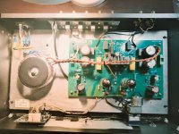
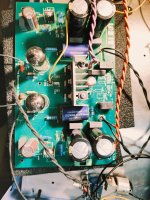
Here is the before...
Here is the before...
Attachments
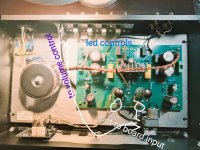

Yes that's the one. They have changed the layout over the years and mine is a rather old version.View attachment 1415636
is this the unit you have?
Have you contacted lab12 to obtain a schematic?I have pics of my before and after but there's no available schematic.
ok so you've replaced supply caps, a new volume control and a input selector?
No, I just assumed they wouldn't but can't hurt to try...Have you contacted lab12 to obtain a schematic?
That's about it, yes. Right now there's just one input with no switching, but there was a switch in there.ok so you've replaced supply caps, a new volume control and a input selector?
as a "noob" myself, I wouldn't try to mess with it unless a schematic was availableNo, I just assumed they wouldn't but can't hurt to try...
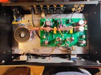
In from RCA, direct to volume control, which goes to (in left) and (right) on the preamp board.
This is the original alps. I'm very confident it's not a wiring issue on the volume itself as I've done it 36 times with two different volume control, one of which I'm currently using as a passive until I fix this...which I was able to successfully wire without issue.
This is the original alps. I'm very confident it's not a wiring issue on the volume itself as I've done it 36 times with two different volume control, one of which I'm currently using as a passive until I fix this...which I was able to successfully wire without issue.
Attachments
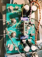
looks as though you changed where the inputs and outputs where originally physically positioned...no big whoop there.
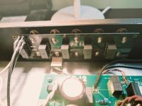
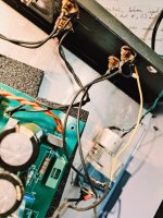
can you get a better pic of your volume control wiring along with the connections at the board?
no offense intended but your solder skills leave a little bit to be desired.
ok most of the preliminary/obvious questions are behind us.
at this point i'll make the usual disclaimer about precautions regarding working on devices containing high voltage.
do you have a DBT (dim bulb tester) as that would be advisable in order to protect your preamp.
how confident are you with checking operating voltages??
I notice the outputs are through relays. Are they making.
Is the selector board still present, and have to switch through. It certainly controls some relays.
Is the selector board still present, and have to switch through. It certainly controls some relays.
What equipment is available? An ac voltmeter? Miswiring the pot is not so unlikely.
I would begin by checking B+ and heater voltages, which are probably fine. Then take the pot out of the circuit by connecting a live signal wire from the input relay board directly to the input pad on the main pcb. Apply 1kHz or similar from a soundcard to the selected input. The spec sheet probably states the voltage gain, something in the region x4 - x10 would be appropriate. Set level at sound card output to 100mV and take a measurement at the output of the preamp. If nothing comes out, make sure the 100mV are present on the main PCB pads where the input is.
In the unlikely event that power is present, input signal is applied to the board and still nothing comes out, we'll get back to the drawing board.
There seems to be an output muting relay, does it click as normal?
I did change those just for convenience.
I'll take pics of those.
My soldering is generally firmly adequate.... bordering in good...this is really just tacked together due to being at the end of my rope.
I do not have a dbt, but maybe I should...I will if I can...
I have not checked the operating voltages. I can watch a quick YouTube and do so.
I did change those just for convenience.looks as though you changed where the inputs and outputs where originally physically positioned...no big whoop there.
can you get a better pic of your volume control wiring along with the connections at the board?
no offense intended but your solder skills leave a little bit to be desired.
ok most of the preliminary/obvious questions are behind us.
at this point i'll make the usual disclaimer about precautions regarding working on devices containing high voltage.
do you have a DBT (dim bulb tester) as that would be advisable in order to protect your preamp.
how confident are you with checking operating voltages??
I'll take pics of those.
My soldering is generally firmly adequate.... bordering in good...this is really just tacked together due to being at the end of my rope.
I do not have a dbt, but maybe I should...I will if I can...
I have not checked the operating voltages. I can watch a quick YouTube and do so.
I notice the outputs are through relays. Are they making.
Is the selector board still present, and have to switch through. It certainly controls some relays.
The inputs are through relays, which I removed. Could that be the issue? It seems to me that board just connects to the selector knob, then to the volume control, then to the main board. Other than connecting to the main board for "led" which I assume is power for the led.
The outputs just seem directly connected.
I was thinking my next move shoukd include just trying to put everything back together as close to original as possible. I still have everything
The output relays, K1 and K2. On the main board, beside the output wires.
This unit looks like an old valve main board, but the input selector switch, looks like a newer circuit board. I can see at least one chip on it. It's not just a manual switch with power for an LED. We could do with a look at it, unless you are sure it's just a chip for switching.
This unit looks like an old valve main board, but the input selector switch, looks like a newer circuit board. I can see at least one chip on it. It's not just a manual switch with power for an LED. We could do with a look at it, unless you are sure it's just a chip for switching.
- Home
- Source & Line
- Analog Line Level
- I broke my preamp and could really use some basic troubleshooting help