Hi Everyone,
I have a pair of 5965's and I wanted to use Jeremy Epstein's
DC coupled Paralleled 1626's Darling. OK here is the Issues, I want to
use my old Wards Transformers and they are a little different than what
Jeremy has. Mine are 2K primary 4-ohm OPT'S His are Hammond 3k 8ohm
So, I wanted to get the Maximum power but stay in safe limits. Jeremy
Epstein used a 8532 I will be using the 5965's 1/2 per channel and I will be
running this like mono blocks in stereo, if thats possible. This is for a
Compression driver amp in a tri-amp setup! Notice the 8uF cap in the signal
path to the 1626's... I want that 2500hz Freq. setpoint for the Compression
drivers which by the way are 4-ohms, which match up with the wards OTL.
I am New at this, and I got my values from the RCA tube manuals and plate curves,
BUT; I really don't know If I got this right and If Anyone can advise some changes
I can amend my schematic. We have taps off of the power supply of 275VDC,
200VDC, 190VDC, 125VDC, at different points along the chain of resistors and caps.
I like having the meters, just cool to see what is actually going on when the amplifier is operating,
So I hope I hooked those up right! Again, I have really been working very very Hard on this
and I have finally found the tubes and design I LIKE just need to make this work somehow!
Thanks and bless You All, Please help me finish this out! PianoLydia
Attachments
Last edited:
ammeter needs to be in series with the cathode resistor. Currently (haha) it is in parallel with the cathode resistor
is your crossover external and between source and amp? If so, why are you putting the 8uf cap in the signal circuit?
Because The crossover is in this case a PLLXO
The crossover will not be between the outputs on the amplifier going to the speaker, This Passive/active situation where the Cap is placed in the Signal Path between the pre-amp and output stage sends only those frequency's to the output transformers will only really see that cutoff frequency and above to be amplified out to the compression drivers.
The crossover will not be between the outputs on the amplifier going to the speaker, This Passive/active situation where the Cap is placed in the Signal Path between the pre-amp and output stage sends only those frequency's to the output transformers will only really see that cutoff frequency and above to be amplified out to the compression drivers.
I just corrected the Ammeter and put in series!
Here I corrected the Ammeters and put those in series with the Cathode
bias. Done! Any more help would be appreciated! Thanks and bless you all!
P.s. Remember I am new, And my friend and I are trying to get this
right, So Please be courteous and Understand this is my First and Only amp I
will be designing, Thanks! pianolydia
Attachments
Not sure where you got this schematic from...
A few points, the grids need a ground reference, or else they will float up on the ends of those coupling caps.
The value of 8.0ufd is way too large. You're going to want a much much smaller cap to make the xover around the frequency you want it to be.
The bypass cap on the cathode resistor isn't going to be of particular value because you want a high pass filter, you can adjust that value to make a sort of gain shelf to help out ur xover idea.
The meter has an internal resistance, you don't want it in series with the cathode. You want a voltmeter that is calibrated based on your choice of cathode resistor - which in turn is set to provide the bias for your particular tubes. The scale on the voltmeter can say amperes (and show the nominal range required). Or you could put an ammeter in the plate lead or in the ground return of the power supply - in the latter case it would show all current drawn, including the first tube, IF you use a single power supply source and only want a relative indicator.
You should be aware that in a class SE amplifier, the current drawn is more or less constant.
FYI, this is likely to only your first amplfier... you'll see...
_-_-bear
Epstein's 1626 Darling has nearly twice the B+ voltage than those indicated on your schematic, that will significantly impact your output power and distortion...

The operating point for the first stage needs to be properly set up. Presently it is 0V on the plate with 8.63mA current: that's impossible.
So I would first look at the B+. 190 V will work but will result in a lot of 2nd harmonic distortion. I didn't draw the plate curves for the 1626, but I expect that there is too little B+ there too.
Here's what I would recommend: use an appropriate power transformer that gives you at least 350V - 400V. Use a B+ of 350V for the 5965 stage and a plate resistor of 50k ohms. Bias the tube at 4mA @ -2.6V; the plate voltage will be 145V.
Attached is some plate curves I drew for my own project. Notice I mislabeled the 130V plate voltages by 5V.
Attachments
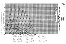
I had a look at JE's schematic and it looks like he is using a B+ of about 260V. That being the case, use the load lines above but change the first stage B+ to 250V use the 50K plate resistor; plate voltage will be about 110V with a bias about -2 for a plate current of about 2.6mA. I would use a red LED for bias and delete the cathode cap.
PALUSTRIS; IS THIS CORRECT NOW!
I did take out the resistor and cap on the 5965's this is what
you were talking about as I gathered your info, Hope it's right. I did Ground the 1626's and the
meter's in place in series. Can you calculate for me the 1626's load curve like you did for your 5965 project, that would nail this thing down and be done! Oh I have included the Wards power supply as well. You will notice the different taps to choose from, only difference is mA are going to be different at the different taps.... Anyway, if you could do this I would be so Happy and be closer to getting this done! Thank you so much PALUSTRIS.... PIANOLYDIA
Attachments
pianolydia,
unfortunately, your present understanding of circuitry is not sufficient for you to redesign an amplifier.
The circuit you just posted has serious errors, and will not function properly.
I would strongly suggest building something that is known to work.
Fwiw, 1625 tubes or 807s or 6L6s, all about the same are not terribly expensive.
Since you apparently have some output transformers in hand, you might want to look around for a circuit that will work well with a similar transformer and power supply voltage. Or just sell the transformers and buy new or used ones that are more suitable to an existing design - of which there are literally hundreds.
Sorry to be taking the air out of your sails, but guessing without at least being able to make an educated guess will not give you something that works properly. Otoh, if you are careful, have a scope and variac/ammeter and a signal source (sine/square wave) for testing, you can learn by doing. However, the voltages in a tube amp are DEADLY and can kill you quite dead.
The schematic I posted is a working example. I took the time to design it from scratch for your tubes and what you stated you wanted it to do. It has the 2500hz high pass incorporated into it that you want for your compression drivers. Build it as is and it will work correctly. As was stated by Bear, you do not seem to have a working knowledge of design and I would not recommend trying to willy nilly a circuit together that operates at these voltages. Best of luck to you.
Thanks Everyone, Yes, I just don't have that working knowlege
Well, first I want to say thanks and "When the bear speaks I am going to Listen!" It did not take the wind out of my sails, But tough Love is Needed, because as Bear stated, 300+ volts Can KILL YOU DEAD! So thanks for the tough love Bear-- Now, Bear, Look at what others have commented and even JERLUWOO Just Posted and have you seen his schematic for my tubes?
Thanks everyone, pianolydia
Just curious about the choice of the 5965, it's not the most linear tube around and it's harder to find than say a plain old 12AT7, any particular reason to use it in this circuit?
I want to keep the 9-pin configuation it's what I had on hand!
12AT7 your right I can use that as well since it is essentially the same tube. usually most military tubes can handle more voltage and has lesser microphonics and better stabilty and thicker glass envelopes, I could consider a different tube say 6CG7, 12FQ7, 6DJ8, 6N1P, 6922, 8542, ETC... People have used the 6SL7 6SN7, 12SN7. What would you recommend then?
12AT7 your right I can use that as well since it is essentially the same tube. usually most military tubes can handle more voltage and has lesser microphonics and better stabilty and thicker glass envelopes, I could consider a different tube say 6CG7, 12FQ7, 6DJ8, 6N1P, 6922, 8542, ETC... People have used the 6SL7 6SN7, 12SN7. What would you recommend then?
No idea really... My comment came largely from simulation results, i.e., not actual listening impression from real circuits! But I read on the Bottlehead forum, that most users prefer other tube types to the original 5965 used in Paramore design... Since you have so many different tubes, you will be the best one to judge once the amp is built and you do some tube rolling ;-)
The Darling was originally a kind of niche amp, to see how cheap you could make an (still very nice) amp with unknown and almost free tubes. Well, they're not unknown or free anymore.
Also there was the idea of distortion cancellation in the original Darling notes.
The 1626 is actually quite good, especially with higher currents - the 20 ... 25 mA range most people use it is not that good.
Go with 35 or 37 mA. It'll take it. I made a lot of Darling variations, and the tubes take 10W dissipation just fine.
As for the driver, I tried 12AU7, 12AT7, 6SN7, 6SL7 and finally a bunch of russian tubes.
Out of the more common tubes, I would go with 6SN7 if you plan on using resistive loads, and 6SL7 if you use a gyrator plate load.
If you're set on 9 pin drivers, I would go russian, absolutely.
The 6N3P would be a fine double triode, cost next to nothing, good linearity with 10mA current and a proper impedance plate load.
Then there's 6N23P, which is similar to 6DJ8 and 6922. Good and cheap.
6S3P is another pretty cheap and fine alternative.
6S45P is very good (somewhat similar to 6S3P) but getting to be expensive these days.
The 6E5P triode strapped is excellent choise for driver. Still affordable even for just experiments. Just remember to put stopper resistors on everything - all the plate connections, all the cathode connections and all the grid connections. Put 47 ohm on everything (not the heater though!). This is the one I would go with if I wanted a 9 pin driver for my amp.
- Status
- Not open for further replies.
- Home
- Amplifiers
- Tubes / Valves
- I am Trying to Design this Darling Amplifier