Hi,
I have just got a SMPS400A180 and 2x UcD180HG/HxR but I'm not 100% sure how I'm supposed to connect the DC error, Auto Amplifier Enable, Amplifier Standby or SMPS Standby connections.
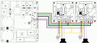
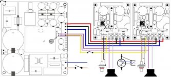
I've attached a diagram. Is the DC Error Input done correctly? It just connects to LS+?
Also, what am I supposed to do with Auto Amplifier Enable, SMPS Standby or Amplifier Standby? I will just be using a switch on the mains input to the SMPS400.
Any help appreciated!
I have just got a SMPS400A180 and 2x UcD180HG/HxR but I'm not 100% sure how I'm supposed to connect the DC error, Auto Amplifier Enable, Amplifier Standby or SMPS Standby connections.
I've attached a diagram. Is the DC Error Input done correctly? It just connects to LS+?
Also, what am I supposed to do with Auto Amplifier Enable, SMPS Standby or Amplifier Standby? I will just be using a switch on the mains input to the SMPS400.
Any help appreciated!
Attachments


I have seen this diagram but what if I want a switch on the mains side so the device is completely switched off instead of on stand-by?
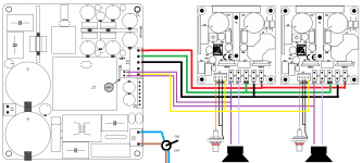
Just updating this thread with how I wired the "auto amplifier enable" connections between the SMPS400 and UCD180s. This way the PSU triggers the amp modules to turn on. I don't think it makes a lot of difference but perhaps if the PSU were to have an internal fault it would stop the AMP modules powering up.
Attachments
Hello,
I am in Canada and I am confused as to how to connect the mains. Does anyone know how to connect both J1 and J2 with 115v mains?
Thanks
Jeff
I am in Canada and I am confused as to how to connect the mains. Does anyone know how to connect both J1 and J2 with 115v mains?
Thanks
Jeff
Madtrapper, you should read the datasheet regarding 115V operation but I think you are correct about J1.
Yes it has a "remote" connector but this is not like a infrared remote if that's what you are thinking? It is to use another signal to tell the PSU to turn on.
Yes it has a "remote" connector but this is not like a infrared remote if that's what you are thinking? It is to use another signal to tell the PSU to turn on.
The datasheets are missing much information. The image on the circuitboard shows the pins connected with 115v. Too bad they label it remote controlled. Very misleading on their part. Preamp it is! Thanks!
Just updating this thread with how I wired the "auto amplifier enable" connections between the SMPS400 and UCD180s. This way the PSU triggers the amp modules to turn on. I don't think it makes a lot of difference but perhaps if the PSU were to have an internal fault it would stop the AMP modules powering up.
Thank's for this wiring diagram.. It helped me a lot ! I'm still trying to figure out if there is some kind of auto shutoff / standby mode and how to activate it.
Greetings
bump ?
How does the SMPS400 or UcD's go into standby (power saving) mode ? Do they sense an absence of signal on the + LS terminal since a pair of cables are connected there from the SMPS ??
Thank's.
How does the SMPS400 or UcD's go into standby (power saving) mode ? Do they sense an absence of signal on the + LS terminal since a pair of cables are connected there from the SMPS ??
Thank's.
Hi,
By any chance could someone help me out with my UCD400 and SMPS400.
I'm sure I have made a really simple mistake, but I just can't see it.
I have wired these two boards together using the attached wiring diagram.
When powered up the HxRs glow red, so they are getting power.
When I close the switch between J3: pin 5 of the SMPS400 and J4 on the UCD400, the blue LED on the UCD400 lights up.
But for some reason the UCD400 itself is playing audio?
Any suggestions?
Thank you.
Ste
Attachments
Seems ok. Blue does mean unmuted, as you know.
Check signal wiring.
Make sure your source is outputting what you think it is.
I'm sure you will solve it, good luck.
Check signal wiring.
Make sure your source is outputting what you think it is.
I'm sure you will solve it, good luck.
Hi,
Thanks for your reply and encouragement...
I'll keep scratching the ole nogging, stare at it for a while longer and see if I can find the problem and let you all know for future diy-ers.
Probably a loose crimp connection or something.
Done a lot of continuity testing with my DMM but i'll keep working on it 🙂
Thanks again.
What is the actual problem? It sounds like it is working correctly. Blue LED means it is working OK.
Sorry my bad, must have forgot that bit.
Despite seeing that blue LED light up.... I can hear that the UCD module itself is still playing the audio . and either no sound, or very very quiet signal out of LS+ and LS-
But I thought the blue LED the indicator it was done.
Any suggestions welcome... I'm gna keep going at it and will keep everyone posted 🙂
Hi all, i think the chaps over at Hypex have found the solution.
They just suggested I may have accidentally shorted the speaker outputs through the chassis.
And I remember drilling the holes in the chassis for the banana plug terminal posts, it was quite snug... so I think that must be it 🙂
Just going into work at the moment, will see if that's the problem either tonight or tomorrow morning and keep yaz posted 🙂.. thanks for everyone's input.
Ste
- Status
- Not open for further replies.
- Home
- Amplifiers
- Class D
- Hypex SMPS400 + 2x UCD180 wiring (DC error, Auto Amplifier Enable, Amplifier Standby)