Babowana your´e right !
Even order distortion worsens and noise gets slightly higher with kenpeters suggestion.
But it is probably not that important as the differences are small
Even order distortion worsens and noise gets slightly higher with kenpeters suggestion.
But it is probably not that important as the differences are small
Noise is not bootstrap, its Aleph's collector overshooting.
Got the fix for that in WFT5, see my other thread P.I.F.A.
Basically Zen for the bipolar. Will then follow maybe a bit
less rigidly, but also far less noisy.
Got the fix for that in WFT5, see my other thread P.I.F.A.
Basically Zen for the bipolar. Will then follow maybe a bit
less rigidly, but also far less noisy.
My last effort. I'm very proud of it.
The 6N6P is actually a double triode, and I have a lot available; so why not to use both of the triode in an envelope for a channel?
So, LTP (long tail pair) looks as a good choice.
But, LTP lowers the gains to half of a single triode, not enough to drive the output stage to full power; so I also added a current mirror on top of the LTP to add some more juice, and voilà I have a great input/driver stage with an inverting input and enough gain to drive the final stage!
One can also add some feedback, now, to make the amp more linear; but I'm not sure it is worth the try.
So, attache the spice file and a jpeg: enjoy them.
Any comment welcome.
Ciao,
Giovanni
Attachments
This is the gate current noise I was referring to.
Caused by Aleph's Collector overshooting the mark.
Not caused by bootstrap. Simmed with your battery.
This was straight from your 005, no modifications.
Let me see if I can fix this by throwing a little Zen
style Schading around that bipolar....
Caused by Aleph's Collector overshooting the mark.
Not caused by bootstrap. Simmed with your battery.
This was straight from your 005, no modifications.
Let me see if I can fix this by throwing a little Zen
style Schading around that bipolar....
Attachments
Strange.... Its just not cooperating no matter how I try.
Thought fixing this was gonna be a whole lot easier.
Just opened a whole new can of worms.
Thought fixing this was gonna be a whole lot easier.
Just opened a whole new can of worms.
Nevermind completely. Now its in mine too.
Thought I had damped that ugly squiggle???
But there its again! I am at a loss to explain.
Thought I had damped that ugly squiggle???
But there its again! I am at a loss to explain.
Rev, this is the wiggle measured at your 007 bias LED.
Funny thing: Cathode bias smooths out into a mostly
normal looking sine with as little as 220uF in parallel.
But this makes the output distort even more ?????
Perhaps I'm just looking at the verge of output stage
clipping, extra gain sends it further over the edge?
Funny thing: Cathode bias smooths out into a mostly
normal looking sine with as little as 220uF in parallel.
But this makes the output distort even more ?????
Perhaps I'm just looking at the verge of output stage
clipping, extra gain sends it further over the edge?
Attachments
Not so very interesting what mystic things happens at the cathode in Spice as this stage works IRL. Have used it with 6H30, 6N6, 6DJ8, 6C45, with different diode strings that is. Simple and stable, sounds better than resistor/cap in my ears !
!
Wonder what would happen with not so ideal caps etc.......
!Wonder what would happen with not so ideal caps etc.......
More interesting yet, how much LTSpice favors a simple
plate bootstrap over an actual constant current source.
THD comes down from 1.712879% to 1.163536%
Mostly in what previously appeared as-if high order
IMD artifacts...
How much of this "improvement" reflects in reality?
I'm betting the gate noise that drove me crazy
earlier is yet another figment of LTSpice's over-
active imagination.
Attachments
In real circuits I get very little difference between bootstrapping
a resistor vs a current source or bootstrapping a current source,
except for the ability to drive the stage rail-to-rail.
😎
a resistor vs a current source or bootstrapping a current source,
except for the ability to drive the stage rail-to-rail.
😎
Hi all,
I didn't forget the thread, I've been very busy with my job and my real life (a daughter, a wife and a dog don't leave you so much free time...).
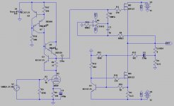
I ended up with a new schematic, the one below.
I tried a lot of configuration and circuit arrangement, from common cathode to LTP and beyond... and decided I like the simplicity of the schematic I'm showing you now.
The circuit sims very well, the THD and the FFT looks very fine (at least to me), and is quite simple.
One can remove the feedback and make it even simpler.
Ciao,
Giovanni
I didn't forget the thread, I've been very busy with my job and my real life (a daughter, a wife and a dog don't leave you so much free time...).
I ended up with a new schematic, the one below.
I tried a lot of configuration and circuit arrangement, from common cathode to LTP and beyond... and decided I like the simplicity of the schematic I'm showing you now.
The circuit sims very well, the THD and the FFT looks very fine (at least to me), and is quite simple.
One can remove the feedback and make it even simpler.
Ciao,
Giovanni
Attachments
The Mu Follower node at R9 top may have lowest "impedance".
But its asymetrically slewed impedance. Pull-up appears infinite,
but pull down no better than your unaided Triode. I see nothing
in next stage that favors this imbalance of slew.
Why you didn't tap drive from the midpoint of r9? Where the
Aleph becomes an equal truly anti-opposite triode in SEPP?
Six one way, half a dozen the other...
------------------------
Good job on Q3. Emitter impedance at Q6 (seen as-if a cascode)
low frequencies can't leak through bootstrap, cause now there
isn't any! But think you could have picked a smaller MOSFET with
lower gate charge. Where Q6 emitter impedance may yet droop
on the high frequency end....
I mean, its only a preamp stage. Does a triode really want to
charge and discharge the full gate capacitance of M2 IRFP240
through the Aleph's emitter? Overkill component choice...
I mean, if the purpose of the Aleph was to help this plate drive
the big gate of an M1 IRFP9240, does it make sense to load it
down (through the cascode) with an equal or larger dynamic
burden than the one you just got rid of?
Hi all,
I didn't forget the topic nor the project, I'm simply too busy with my job, my daughter, my wife, my house, my dog...
OK, I found a bunch of IRF122 mosfet in one of my scrapboxes in my garage, so why not to use them for this project?
I can use them as a source follower, they should be good enough for the job.
The only problm is I need a complementary P-channel mosfet or bipolar for the active current source... But do I really need it?
I had a food idea (in my opinion, at least), and realized an output stage that uses only N channel mosfets (2 IRF122), keeping the Nelson Pass Active current topology.
Other advantage is we do not need anymore any bootloader for the ACS mosfet.
Attached LTspice schematic.
Ciao,
Giovanni
Attachments
Other advantage is we do not need anymore any bootloader for the ACS mosfet.
Sorry, what I meant was "boot strapped circuit"; I'm a programmer, other than an electronic engineer, so the wrong word...
It simulate very well, even better than myu previous schematics on this thread.
And here is the schematic.
Ciao,
Giovanni
Attachments
Old thread, but not dead.
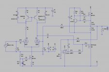
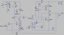
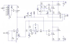
I continued in my research, and I ended up with a very simple but very nice amplifier project.
I discarded the source follower and went back to a more "canonical" Aleph output topology... but keeping the input tube.
Added also "a lot" of feedback, and it seems it is worth the effort.
I also moved to a parallel output mosfet topology, which seems to lower the THD.
The circuit below simulates amazingly well in LTspice (better than the original Aleph Mini, actually); I'm now in the process of building one prototype, just to test it.
I redrawn the circuit with Eagle, and now I'm drawing a PCB I can build the prototype on.
I will let you know how it will work in real world.
Ciao ciao
Attachments
- Status
- Not open for further replies.
- Home
- Amplifiers
- Pass Labs
- Hybrid with Nelson topology