I was wrong, or at the very least incomplete. A1 "drives" R11 with a source impedance of R2 = 10K Ohm. 10K + R11 (=6k8) feed the summing junction, current into the junction is zero'd by current from R5. So signal from A2 is smaller by 10K / 16K8. I'm sorry to have posted in error.
All good fortune,
Chris
You are right. I thought the currents would be reasonably but not perfectly balanced, but when I calculate it, there is a very substantial difference.
@Sorento Do you intend to only drive this circuit from a single-ended source or also from balanced sources? I'm sure there must be a way to get the output currents of the transistors reasonably well balanced by changing the values of R5 and R13, but then it won't work with balanced sources anymore. A circuit with a tail current source could work for both balanced and unbalanced sources.
If I calculated it correctly, this should work for single-ended drive, and only for single-ended drive:
R3 = R4
R5 = R2 + R11 (1 + (R2 + R3)/R12)
R13 = R12 (R3 + R5)/(R2 + R3)
Keeping everything else as it was, that means R5 = 17980 ohm and R13 ~= 113986.4407 ohm.
The nearest standard values are 18 kohm and 120 kohm (E12), 18 kohm and 110 kohm (E24) or 17.8 kohm and 113 kohm (E96). I haven't tried to calculate the effect of rounding to standard values.
Last edited:

I was playing around with the simulation and came up with the same values, they do indeed balance the phase splitter
@MarcelvdG :
hah, math and understanding rule, thank you very much for your time and effort;
clipping is now also symmetric and 2nd harmonics cancel as they should;
build it ? don't know yet, maybe prototype one channel just for fun ...
hah, math and understanding rule, thank you very much for your time and effort;
clipping is now also symmetric and 2nd harmonics cancel as they should;
build it ? don't know yet, maybe prototype one channel just for fun ...
What happens when you increase the grid leak resistors now? Maybe the designer made them small to reduce the common-mode impedance to reduce the effect of the imbalance (rather than just solve the imbalance). The (differential) shunt feedback should become more effective with larger grid leak resistor values.
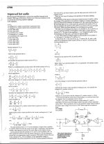
The original article by Jeff Macaulay. p856
https://worldradiohistory.com/UK/Wireless-World/90s/Wireless-World-1995-10-S-OCR.pdf
https://worldradiohistory.com/UK/Wireless-World/90s/Wireless-World-1995-10-S-OCR.pdf
@jhstewart9 :
thanks you, do you happen to know whether there was - in a later issue a month or two later - an errata note or reader' s response which addressed the balancing issue ?
thanks you, do you happen to know whether there was - in a later issue a month or two later - an errata note or reader' s response which addressed the balancing issue ?
Will try ...What happens when you increase the grid leak resistors now? Maybe the designer made them small to reduce the common-mode impedance to reduce the effect of the imbalance (rather than just solve the imbalance). The (differential) shunt feedback should become more effective with larger grid leak resistor values.
I agree the grid leaks are suspiciously low (60kohm/100nF), when the author claims bandwidth down to 5Hz ...
but on the other hand I don' t get 32 W either, clipping seems to happen just below 20;
and I still have to see the advertised 0.07% THD, 0.2% at 1W is the best I get in sim.
And a kind of gross cross over distortion when the transistors go in and out of saturation and the valves enter / leave class A.
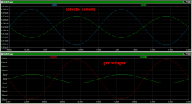
My bad not being able to find the root for the balancing problem was that my focus was on AC voltage balance when the key issue is AC currents; V/ I - I/V conversion is what its all about ...
Same thing I found quite a while back while trying to analyze self inverting PP pairs.when the key issue is AC currents; V/ I - I/V conversion is what its all about ...
The OPT forces the voltages to measure the same, but the currents are very different if the balance is poor.
I'm was working on a Sim of the Baby Huey last night to sort out why it runs well. Same thing,
The Sim results will go into a separate thread soon.😀
@jhstewart:
excellent ! thank you !
although I prefer the simpler math of @MarcelvdG and @Chris Hornbeck;
the proposed mod seems to work well, but gain is way up 10x.
It looks like replacing the 100 ohm balancing resistors with 1 kohm restores the original sensitivity of 1Vp / full power.
excellent ! thank you !
although I prefer the simpler math of @MarcelvdG and @Chris Hornbeck;
the proposed mod seems to work well, but gain is way up 10x.
It looks like replacing the 100 ohm balancing resistors with 1 kohm restores the original sensitivity of 1Vp / full power.
Last edited:
Close, but not exact, see post #24; R12 affects it. Actually post #24 is only exact with infinite loop gain, zero impedance for C4 and equal hfes.R5 should be = R2+R11 so that you have a unity gain inverter at A2.
Last edited:
For me, this is the strong take-away from this thread. It has great relevance for the trendy "Schade feedback" amplifiers in push-pull, like the Baby Huey class.The transimpedance feedback doesn't work at all for common-mode signals when the primary windings of the transformer are perfect and perfectly coupled. Presumably it doesn't work well when they are imperfectly but still quite strongly coupled.
Much thanks as always,
Chris
As it would be so easy to configure one half as a non-inverting amplifier and the other one as an inverting one with identical gain, using precise resistors, I'd consider this design, with due respect, as a crutch. What was the designer thinking? Why did he do it that way? Just to be different? 🤔
Best regards!
Best regards!
Ya, fair enough. I would handle the bias differently and eliminate R12 and R13. My point was that R5 cannot be the same as R2. And 20% was "close enough" for tube amps.Close, but not exact, see post #24; R12 affects it. Actually post #24 is only exact with infinite loop gain, zero impedance for C4 and equal hfes.
- Home
- Amplifiers
- Tubes / Valves
- Hybrid Transimpedance Tube Amp Sim