I've started looking at the electronics bit now...
It would appear the step-up transformer is usually somewhere between 50:1 and 70:1.
Transformers seam to be somewhat costly and difficult to find. Any good suggestions?
Two 230V -> 6V trannies seams to be the cheap way of doing it? The most common variant looks to be the 2x115V | 2x6V but I'm not really sure how to hook it up?
I really don't know how high I want to go? Sure a higher ratio will get me the voltage but it'll put some serious demands on the current abilities of the amp?
How much current is normal for an amplifier to deliver? (How long is a bit of string...)
How much polarizing voltage is normal? People around here seam to use pretty low voltages if I'm not misstaken. I was thinking 8-10kV but I've seen referenses to 2-3kV?
(8" x 48" panels, 80mil d/s spacing, trying to find 1/16" perforated aluminum sheets with +40% open area.)
I've started looking at the electronics bit now...
It would appear the step-up transformer is usually somewhere between 50:1 and 70:1.
Transformers seam to be somewhat costly and difficult to find. Any good suggestions?
Two 230V -> 6V trannies seams to be the cheap way of doing it? The most common variant looks to be the 2x115V | 2x6V but I'm not really sure how to hook it up?
I really don't know how high I want to go? Sure a higher ratio will get me the voltage but it'll put some serious demands on the current abilities of the amp?
How much current is normal for an amplifier to deliver? (How long is a bit of string...)
How much polarizing voltage is normal? People around here seam to use pretty low voltages if I'm not misstaken. I was thinking 8-10kV but I've seen referenses to 2-3kV?
(8" x 48" panels, 80mil d/s spacing, trying to find 1/16" perforated aluminum sheets with +40% open area.)
I would definitely opt for a tandem of 50VA 230v/2x6v toroidal trannies if you can find them, as they perform exceptionally well and there would be only a single secondary winding. The 2x115v/2x6v trannies should be equivalent and i have tried some with good results but you just never know how good the insulation is between the 115v windings (which will be the high voltage side) and the insulation between the two 115v windings would typically only be flash tested to 500v (insulation between primary/secondary windings is typically flash tested to 4kv). In any case, the 6v amp-side windings would be wired parallel and the stator-side windings would be wired in series with a center tap to the bias supply.
If you search the forum here, Calvin has posted a lot of good info on using inexpensive toroids for the step ups.
With 80 mil d/s spacing you won't need 8kv bias,--- im thinking 2kv to 3.5kv would be sufficient and less prone to arcing and buzzing.
Aluminum stators would work fine but steel has it's advantages (you could solder on your wire connection, insulating paint stick to it better, it's cheaper and also less prone to ringing).
Good points on the steel vs aluinum stators. How about stainless? It would be nice not having to paint it.
I've had such a good experience with Antek that I'd probably try their 50VA AN-0506. (2x115V, 2x6V)
Otoh looking in the Farnell catalog I find a Multicomp CFG050/06 (50VA, 1x230V, 2x6V) for reasonable money. Save me some money on shipping...
However a single trannie only give you a 38:1 step-up.
I guess we're talking two transformer in series for a total of 77:1 step-up?
Will the 6V side of the second transformer handle the high voltage from the first transformer? I guess it will or you wouldn't be recommending the combo in the first place. 😉
A <3.5kV bias sounds manageble. Will a higher bias result in better sensitivity for the speaker?
I'll see if I can find some of Calvins threads. 😀
My blogpage (address shown below) shows a wiring schematic for the Multicomp trannies and simple bias supply I'm currently using with my hybrid ESLs. The cheap simple bias supply shown works fine with my 60 mil d/s spacing but for 80 mil spacing you would need to add at least one more stage to the multiplier ladder--- this would be quite easy to do by just tacking on two more diodes and caps for each additional multiplier stage (all else remains the same). Also, the small input tranny in my bias supply has four 115v windings wired parallel on the input side and series on the output side to step up my 115VAC house voltage to 230v ahead of the diode/cap stages. If the house current where you live is already 230v, then you would need to wire both sides of the bias supply's tranny in parallel so that you get would still get 230v out.
The Jazzman's Electrostatic Loudspeaker Page
The Jazzman's Electrostatic Loudspeaker Page
Good points on the steel vs aluinum stators. How about stainless? It would be nice not having to paint it.
Even though Roger Sanders' Cookbook says it's OK to leave perf stators unpainted/un-insulated, I would certainly paint them for safety and to make them less prone to arcing. Even with painted stators, I would use grill covers if there were children in the house.
Sanders' book is a wonderful resource but I think it missed the mark with it's recommendation to use .020 aluminum perf for stators. I've placed my hand on a stator in operation and felt it vibrating considerably so I know that stators ring in operation. I would say that ALL stators ring (especially flat ones) and thicker stators should ring less because of the higher mass. It follows that steel would ring less than aluminum for the same reason. Also, aluminum is actually stiffer than steel so it's resonant frequency would be higher-- and perhaps more objectionable. My thoughts on stators has evolved quite a bit recently (after listening to 22 gauge stators for month or so)-- I now believe that steel perf is best and I wouldn't use anything thinner than 20 gauge (.036 thickness) for a flat stator.
I'm having some problems locating the equivalent of 1/16" perf metal suitable for the task.
As it looks right now I can get 2.0-3.0 [mm] (40.3% OA) and 3.0-4.0 [mm] (51% OA) perf steel. (1mm thick)
How much would a powdercoating build on a stator? How much will it reduce the open area?
As it looks right now I can get 2.0-3.0 [mm] (40.3% OA) and 3.0-4.0 [mm] (51% OA) perf steel. (1mm thick)
How much would a powdercoating build on a stator? How much will it reduce the open area?
Doesn't anybody build like Mike Wright using plastic frames? Think of 48 inch fluorescent ceiling lights with 1/2 inch deep open-cell plastic covers composed of 1/2 inch squares. He painted metal on the edges of one side. Ends up being a quite rigid large expanse. On some iterations, he added steel reinforcement and/or damping pieces too. Seems to work good.
hello buddy
I have had extensive pleasure with my panels that Charlie and I built. I am still reading this thread, but if you consider a hybrid, i have a post somewheer here, esl start to finish, with plenty of pictures.
Take some and check it out, as well as Charlie's blog page, we both use the same set-up, only different eqipment(amps and such).
Sorry I have been off the grid for a while, look forward to new and happy DIY'ers. Mavric
I will have to defer to others to answer that question, as I don't have the means to actually measure the output of my panels. My impression, however, is that a 4ft2 panel with 1/16 d/s spacing and 1:70 or so step up ratio driven by moderately powered amps will easily play loud enough to suit most people.
I'm bi-amping my hybrids with a pair of 225W/channel Carvers and 1/3 throttle is about all I can stand (they'll blow women's panties right off).
My friend Mavric has similar hybrids bi-amp'd with a pair of 100W/channel Adcoms and they rock n' roll pretty good.
If you look at Sheldon Stokes' ESL 1.0's, his panels are almost certainly less efficient than mine, since he's using twice the d/s spacing (1/8"), yet he powers them with a pair of 30W tube amps and they apparently play loud enough to suit him.
When I was building my first set of panels I was very worried that 12x48 might be too small but my worries turned out to be unfounded, as they are much more efficient and dynamic than I had imagined. In fact, my 4ft2 panels can easily overpower the 10" woofers past a certain volume level so I later augmented them with subwoofers for when I want to play my jazz really loud.
I have had extensive pleasure with my panels that Charlie and I built. I am still reading this thread, but if you consider a hybrid, i have a post somewheer here, esl start to finish, with plenty of pictures.
Take some and check it out, as well as Charlie's blog page, we both use the same set-up, only different eqipment(amps and such).
Sorry I have been off the grid for a while, look forward to new and happy DIY'ers. Mavric
I'm having some problems locating the equivalent of 1/16" perf metal suitable for the task.
As it looks right now I can get 2.0-3.0 [mm] (40.3% OA) and 3.0-4.0 [mm] (51% OA) perf steel. (1mm thick)
How much would a powdercoating build on a stator? How much will it reduce the open area?
I don't have any experience with powder coated stators but others on the forum do-- so if you post a new thread with "powder coat" in the title I'm sure someone will advise you on that.
Spray painting is not very efficient at building coating thickness inside the holes because the spray gun (or spray can) can't be held perpendicular to the sides of the holes-- so most of the coating thickness builds up on the faces of the stator and far less inside the holes. For example, my sprayed stators have about 12 mils coating on the faces but only 2-3 mils on the side walls of the holes. This I know because the holes measured .125" diameter before painting and are now .119" -.120" diameter after painting.
The conventional wisdom (and Sanders' Cookbook) says that that 50% open area is best but there is some debate about that. Panasonic Corp. did some testing on electrostatic tweeters and determined that 42% open area yielded the highest efficiency. My stators were .048" thick & 40% open before painting and they sound good so I'm comfortable recommending 40% open if the stators are to be spray painted.
My guess is that powder coating would build more coating thickness inside the holes than you would get with spray painting because the powder coating process uses an electrical charge to pull the powder onto the metal surfaces. If so, there would then be less open area after powder coating as compared to spray painting; in which case, it may be best in that case to go with 51% open area stators. Again I will say that I have no experience with powder coating so I advise you to seek advice from others who do.
I think you should post a new thread asking for advice specifically about stator thickness and open area reduction with powder coating.
Good luck with it!
I have to agree. Coating my panels was alot of waste, i guess i am lucky that there has never been insulation issues as far "arching". Charlie has far more experience than me, and I would take what ever he advises, otherwise, I would not be listening to my own(hybrid). I wish you well, and I was very fortunate to have someone hands on on with me, Charlie.
As far as powder coating, my concern with mine was being brittle, so as advised, ask ALOT of questions about coating.
and you do have children or animals, cover them and the step ups, thats some serious voltage( my kitty cat found that for me, cats ok) .
good luck, Mav.
I guess we have strayed somewhat from the original topic. I asked where I could cross over the panels and I did kind of get my answer. A low cross will possibly be ok but maybe not optimal. I have to build them, measure them, tweak them and then we'll know. Not really a big problem, any electronics can be re-used if I need to redo the first set of panels.
However I'm happy that the thread has strayed since I've had a chance to learn so much more from you guys. 😀
However I'm happy that the thread has strayed since I've had a chance to learn so much more from you guys. 😀
Hi,
RV3/4 punched steel sheets is a common standard as well as RV5/6.
(RV means round holes in staggered rows. First number is hole diameter, the second stands for teh distance of the hole mids).
RV5/6 was the pattern ML used before their introduction of the micro-perf stators which seem RV3/4 to me. The larger pattern was probabely the cheapest they could get and the larger holes make the coater´s work a bit easier. Technically as well as acoustically the smaller pattern is slightly better, especially with small d/s values below 2mm.
jauu
Calvin
Thanks Calvin for that information. 🙂
I suppose it can't be all bad if ML is using it. 😉
Rv 2-3 might be another possibility but Rv 3-4 is much much easier to get.
Rv 3-4 has a good OA of 51% and thats allways nice.
I suppose it can't be all bad if ML is using it. 😉
Rv 2-3 might be another possibility but Rv 3-4 is much much easier to get.
Rv 3-4 has a good OA of 51% and thats allways nice.
sorry
I allways have a bad habit of dropping in on toppics as I can only read once ever week so. My stats are crossed over @500hz @24db slope with a Behringer Super Pro cx2310 running stereo with two very old Adcom amps.
As well as a powered sub to take the load off off my TL's. Once again, sorry for dropping in on your post. But some advice, CharlieM has a blog page that has the places to get "all" the material needed to build a complete set, i have so say the most intellegant person I have ever met, not to mention all the help and support.
Ihave a start to finish esl loaded with pics on this site, if you like, check it out, i did my best to explain each and every pic. My first build of something "exotic"! and i have to say "I love it." Mav
I know i am vauge, but I hope this helps you, Mav.🙂
MarcusG
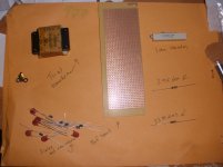
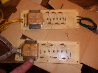
here are a few pics of the step up that CharlieM and built. PIc 2270153 has all the parts needed, you can find the souce @ jazzman-esl-page.blogspot.com . pic 2280164 is the finished top version, Charlie has built the top one, alot better than mine. Fuse holder-tranfomer-resistor-diodes-took about twenty minutes to make and cost 50usd for both.
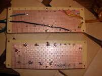
pic 2280165 shows the solder joints made the you can compare with web site for a better idea if you like schematics, a pic is worth a thousand words.
To be honest, I am just so happy with mine that I want to share it, I have read the entire post and I myself did not want to start small, i wanted the biggest and best sounding, I have it now, thats my experience and it was awesome building something i am listening now as I am typing, mine are 16" by 40" stator, 1/16 d/s, 2k, 51% O/A, .0005 micron diagphram coated with Licron. You know the rest. Later, hope the pics help.
here are a few pics of the step up that CharlieM and built. PIc 2270153 has all the parts needed, you can find the souce @ jazzman-esl-page.blogspot.com . pic 2280164 is the finished top version, Charlie has built the top one, alot better than mine. Fuse holder-tranfomer-resistor-diodes-took about twenty minutes to make and cost 50usd for both.
pic 2280165 shows the solder joints made the you can compare with web site for a better idea if you like schematics, a pic is worth a thousand words.
To be honest, I am just so happy with mine that I want to share it, I have read the entire post and I myself did not want to start small, i wanted the biggest and best sounding, I have it now, thats my experience and it was awesome building something i am listening now as I am typing, mine are 16" by 40" stator, 1/16 d/s, 2k, 51% O/A, .0005 micron diagphram coated with Licron. You know the rest. Later, hope the pics help.
Attachments
Thanks for the pics and the tips. I don't mind the thread going OT as long as it's about building ESL's. It saves me the trouble of keeping multiple threads. 😉
I have a gift but it's sometimes a curse. I almost always start with the overall perspective and try to fit the pieces togeather i my mind before I throw any mony into the project.
This time it's the "fitting the ESL with a bass module" that's giving me the most grief.
If there were some clear cut rules to follow it would be a lot simpler.
Interactive Frequency Chart - Independent Recording Network is an interesting page.
The bass range is supposedly below 300Hz, female vocalists have their usual fundamental range between 300Hz and 1kHz.
A kickdrum roughly 40-500Hz and a bass 30-350Hz.
Male vocals 100-900Kz.
Reading my ESL book it's recommended I cross at approximately 500Hz while you guys have told med it's ok to cross much lower, maybe as low as 200Hz even? The lower I cross the less sensitive the speaker and the more membrane movement.
If I cross at 200Hz I could go with a TH but crossing at 500Hz I'll have to try a TL.
To get the bass I'm looking for I think a 10" would be the right size. Doing some quick calculations it would seem the cabinet will end up in the 24-28" range but it could easily be as tall as 40" depending on the build. Width between 10-16" and depth in the 24" area.
The ESL should be as wide as possible and fit the bass module and at the same time the bass module will offset the ESL vertcally putting a limit to the height of it.
At the same time it would be nice to bild the ESL big enough to use floorstanding if I feel the urge to experiment with different woofers.
So, the question remains: Where do I want to cross it and how big can I build it? Too big and the girlfriend won't let me into the living room... Too small might risk the sound.
Sorry for my long rambling but I'm trying to fit the pieces togeather and I'm getting closer but it's taking some time. Last night I found a driver that seems to fit great in a small TL. I'll have to run some more sims before I can say anything for certain.
1. Why don't you simply take for granted that your first try will be badly flawed and so a learning experience from which you can salvage something.
2. Adding an ESL driver to another ESL driver (later) seems easier to do acceptably and smoothly and seems less challenging than other kinds of pairings.
3. Therefore start with a broad tweeter (1000 kHz) ESL, cone(s) below, and take it from there later.
4. Take Point 1 for granted.
2. Adding an ESL driver to another ESL driver (later) seems easier to do acceptably and smoothly and seems less challenging than other kinds of pairings.
3. Therefore start with a broad tweeter (1000 kHz) ESL, cone(s) below, and take it from there later.
4. Take Point 1 for granted.
Reading my ESL book it's recommended I cross at approximately 500Hz while you guys have told med it's ok to cross much lower, maybe as low as 200Hz even? The lower I cross the less sensitive the speaker and the more membrane movement.
If I cross at 200Hz I could go with a TH but crossing at 500Hz I'll have to try a TL.
I assume you are referring to Roger Sanders' Cookbook. It could be that Sanders' thinking has evolved since he wrote the Cookbook because his later day Eros speakers used a 330Hz crossover on the origininal Model 10 and he currently uses a 172hz crossover in the Eros Model 10C, which is a 10" woofer in a TL.
- Status
- Not open for further replies.
- Home
- Loudspeakers
- Planars & Exotics
- Hybrid ESL, suitable x-over frequency?