Hi all,
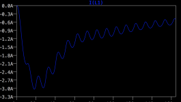
I'm working on a tube amp project and while simulating I noticed that I must solve this issue. At startup I have a big current spike in the ps choke. Something like 3.5A, that would surely knock out the choke. And maybe rectifiers.
I need a circuit of sorts that slowly fills the caps then goes short circuit. Any ideas?
I don't need this to protect the tubes until they are warm or sorts like that. I need it not to blow my PS.
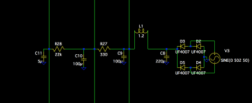
I attached my PS schematic and current through L1 choke.
I'm working on a tube amp project and while simulating I noticed that I must solve this issue. At startup I have a big current spike in the ps choke. Something like 3.5A, that would surely knock out the choke. And maybe rectifiers.
I need a circuit of sorts that slowly fills the caps then goes short circuit. Any ideas?
I don't need this to protect the tubes until they are warm or sorts like that. I need it not to blow my PS.
I attached my PS schematic and current through L1 choke.
Attachments

no worries, your PS won't blow up
1st your xfrm secondary has resistance, measure it and put it in your sim
2nd your choke has resistance, measure it and put it in your sim
peak current will go down
3rd your choke can easily stand even 3 amps for a half cycle, there is a pound of copper in it which takes a lot of time to heating up to melting
4th even if your choke is rated for just 100mA, the wire is usually much thicker than that
5th you rectifier diodes have a surge current spec of 50 amps or so for a half cycle, they won't blow up either
no need for soft start - most amps are built like yours and without soft starter
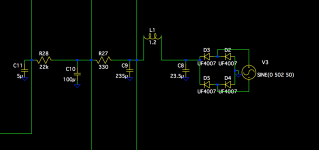
The choke DC resistance is added to the schematic. I didn't add the transformer resistance, but I just remembered that I got it from the company that is making my transformer.
The choke is something custom wound from few years back when I was working on a EL84 amp that never finished.
"Seems" like a 1.2-1.3H choke, with about 200mA rating. I did some tests with my lab ps and heat meter and I noticed a spike in temperature past 250-300mA. At 350mA after half hour the meter showed 40 degrees C above ambient with the sensor directly on the copper (found a small exposed area where I poked the sensor into).
So I might make another one that uses thicker wire. The DC resistance of the choke is about 45ohms as it stands now.
The first cap is made out of two 470uF/400V caps in series with resistors across each. So the voltage spike should be handled ok.
So, basically you say not to worry?
with the added dc resistance on the transformer secondary the spike went down to about 2.7A peak.
The choke copper wire is about 0.3-0.35mm thick.
Last edited:
Sometimes a good idea to crosscheck with another simulator - many find PSUD2 is very quick for that purpose, and provides advise on how to determine effective transformer resistance - something that was once in diode datasheets, but alas no more!
Effective transformer series resistance comes from primary and secondary windings, not just secondary.
This is a capacitor input PS. I'm sure you know that. I would lower the first cap to about 20 uF. That will lengthen the conduction angle and decrease the current peaks not only on the first cycle but on all cycles. That is a very good thing. Then compensate by increasing the capacitance on the second cap.
The reason I said 20uF is that there is a zone from 10uF to 0F where the circuit transitions from a cap input power supply to a choke input power supply. In that zone output voltage is not well regulated and will vary with dc current draw. 20uF puts you safely above that zone, but still lowers current surges.
The reason I said 20uF is that there is a zone from 10uF to 0F where the circuit transitions from a cap input power supply to a choke input power supply. In that zone output voltage is not well regulated and will vary with dc current draw. 20uF puts you safely above that zone, but still lowers current surges.
Last edited:
This is a capacitor input PS. I'm sure you know that. I would lower the first cap to about 20 uF. That will lengthen the conduction angle and decrease the current not only on the first cycle but on all cycles. That is a very good thing. Then compensate by increasing the capacitance on the second cap.
The reason I said 20uF is that there is a zone from 10uF to 0F where the circuit transitions from a cap input power supply to a choke input power supply. In that zone output voltage is not well regulated and will vary with dc current draw. 20uF puts you safely above that zone, but still lowers current surges.
I want to make an addition to the current setup without affecting the PSRR of the power supply. I presume lowering the first cap would rise the ripple on subsequent stages?
I know it is a capacitor input and not choke input power supply.
I want to make an addition to the current setup without affecting the PSRR of the power supply. I presume lowering the first cap would rise the ripple on subsequent stages?
I think that is an unnecessary requirement to make every stage have a high PSRR. As it's designed now almost all the REAL load is being born by that first cap. You want to lessen it. You can make up for any shortfall in overall ripple rejection by increasing the second cap's capacitance. That is a more reasonable objective and will lower the noise floor of the amp. That's because even during steady state operation, as it's designed now, you will have very short, extremely high pulses going to that first large cap as it tops up. You want to lengthen the time of that "topping up" by decreasing its capacitance.
Last edited:
The sad part is that I already bought the first caps (two in series), and the the second cap. And they costed quite a bit.
I presume I could use the first cap arrangement (two in series) on the second cap position. That would up the capacitance from 100uF to 235uF for the second position. And add a lower cap on the first cap position (two in series). Something like 2x47uF?
I presume I could use the first cap arrangement (two in series) on the second cap position. That would up the capacitance from 100uF to 235uF for the second position. And add a lower cap on the first cap position (two in series). Something like 2x47uF?
Yes, that should probably work. Don't quote me on that though. There are complications when putting caps in series, such as load balancing between them. However that would have been the case even in the first design. I wouldn't feel bad though. I've run through so many designs in progression as I've learned more that it's ridiculous. Sometimes that learning was after I've bought the parts, just like you.
Hehe, I don't mind. I'm in this for learning, I find it fascinating 🙂
It's a small price to pay for knowledge.
I already bought some 120K resistors for balancing the voltage on them. I'll do the same on the second pair.
It's a small price to pay for knowledge.
I already bought some 120K resistors for balancing the voltage on them. I'll do the same on the second pair.
This is a capacitor input PS. I'm sure you know that. I would lower the first cap to about 20 uF. That will lengthen the conduction angle and decrease the current peaks not only on the first cycle but on all cycles. That is a very good thing. Then compensate by increasing the capacitance on the second cap.
The reason I said 20uF is that there is a zone from 10uF to 0F where the circuit transitions from a cap input power supply to a choke input power supply. In that zone output voltage is not well regulated and will vary with dc current draw. 20uF puts you safely above that zone, but still lowers current surges.
Actually the current surge increased from 2.7A to 3A. I presume the surge is because of the second cap? The lower that cap, the lower the surge.
I tried 20u, 10u, 5u, 1u, 0.1u and 0.00001u, same thing, 3A surge. There's the wrinkles that are different from my original setup, but besides that, nothing. The surge increased actually because I upped the second cap. All DC resistances are in place, from transformer and choke as well.
You see, I am not lowering the second cap beyond 100uF no matter what.
So off to the drawing board again.
Attachments
Last edited:
Well, we are probably talking about two different things actually. The surge protection for start up is a good idea. I never said it wasn't. What I was suggesting is that in addition that first cap is too big. I think there may be something about the value of that choke that is causing it to ring on startup. When I've played with power supplies on PSUD I would get that same kind of thing sometimes with high values of inductance in the choke. Play with it in the simulation and see if it goes away. The surge protection will help with that, in any case.
Again, the first cap is too high and should be reduced but I doubt that it is causing what you are seeing. That first cap value is more of a steady state problem and is not what is causing what you are seeing.
Again, the first cap is too high and should be reduced but I doubt that it is causing what you are seeing. That first cap value is more of a steady state problem and is not what is causing what you are seeing.
Effective transformer series resistance comes from primary and secondary windings, not just secondary.
Transformer specifications include an impedance figure which indicates the secondary voltage drop between zero and full rated load.
This takes into account winding resistances and magnetic losses.
This is specified in %Z and can be 10% or higher for a small transformer.
From this you can work out the series impedance for your model.
Frank
I suggest Trileru get to know and use PSUD 2. Here's the link:
PSUD2
One advantage of using it is that it's free. But the biggest advantage is that it's very simple to use and encourages appropriate data inputs for the components. For instance, you don't have to know inductances of the power transformers. In real life you don't have to know that stuff. You just have to know the appropriate output voltage and the power rating of it. It also encourages simplification by excluding the load circuits and instead just putting in either a resistance or a constant current sink. I suspect there is a misrepresentation of some component or components in Trileru's simulation program.
But I could be wrong.
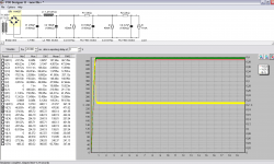
I was curious as I did get the current spike in LTSpice and after checking I noticed that the "Soft start" option was checked in PSUD.
After I ran the simulation without that option seems like I get the same current spike on the choke. So...seems like I get the same results as LTSpice.
I guess that I can safely assume that I will have a current spike in the practical application of this circuit, and I need to deal with it.
LTSpice gives about 3.5A and PSUD gives 2.6A. Between them there's a large current spike.
If in the practical application this doesn't matter much, I will ignore it. If it endangers my choke, I could try and deal with it. What does anyone recommend?
Attachments

Last edited:
- Status
- Not open for further replies.
- Home
- Amplifiers
- Tubes / Valves
- HV soft start